<?xml version="1.0" encoding="utf-8"?><feed xmlns="http://www.w3.org/2005/Atom" xml:lang="en"><generator uri="https://jekyllrb.com/" version="3.10.0">Jekyll</generator><link href="https://satharus.me/feed.xml" rel="self" type="application/atom+xml" /><link href="https://satharus.me/" rel="alternate" type="text/html" hreflang="en" /><updated>2026-03-16T16:05:39+02:00</updated><id>https://satharus.me/feed.xml</id><title type="html">Technoir - Blog of Satharus</title><subtitle>Computer Science – Cybersecurity. Things I find interesting.</subtitle><author><name>Ahmed Elmayyah</name><email>a.elmayyah@gmail.com</email></author><entry><title type="html">Milk, I2C, and SMBus</title><link href="https://satharus.me/tech/2024/08/27/i2c_milkv.html" rel="alternate" type="text/html" title="Milk, I2C, and SMBus" /><published>2024-08-27T00:00:00+03:00</published><updated>2024-08-27T00:00:00+03:00</updated><id>https://satharus.me/tech/2024/08/27/i2c_milkv</id><content type="html" xml:base="https://satharus.me/tech/2024/08/27/i2c_milkv.html"><![CDATA[<p>Last week, a friend of mine gave me an interesting single-board computer with the goal of getting it to communicate with another chip he was working with over I<sup>2</sup>C. The SBC is quite small. It has 2 RISC-V cores, an ARM core, and a whopping 512 megabytes of RAM…
<!--more-->
It can also run RTOS and Linux simultaneously, and has an open source SDK. For just under £10, I really can’t complain much. I am talking about the <a href="https://milkv.io/duo-s">Milk-V Duo S</a>.</p>

<p>Now you may be wondering, what does milk have to do with RISC-V? I honestly have no clue. Anyways, we have a cheap SBC, half-baked documentation, and a drea… I mean a goal of running I<sup>2</sup>C code functionally on it.</p>

<p class="info">Inter-Integrated Circuit (or I2C/I<sup>2</sup>C/IIC for short) is a synchronous serial communication bus. It consists of two lines, a data line, and a clock line.
It is designed to have a single controller (AKA master) and many peripherals (AKA slaves). Each peripheral has its own address and the controller has to address the peripheral first before sending any data. I could go into lots of detail on how I<sup>2</sup>C works, though I’d rather have you read this <a href="https://learn.sparkfun.com/tutorials/i2c/all">tutorial from SparkFun</a> as it is very thorough.</p>

<p style="text-align:center"><img src="/assets/images/i2c-milkv/I2C_Example.png" alt="" /></p>

<p style="text-align:center">From PulseView using a Sipeed Logic Analyser, an example of I<sup>2</sup>C communication where the controller sends <code class="language-plaintext highlighter-rouge">0x76</code> represented as a 7-bit number, followed by a <code class="language-plaintext highlighter-rouge">0</code> bit (indicating a write) and then proceeds to write the value <code class="language-plaintext highlighter-rouge">0xF7</code> as a single byte of data to the peripheral</p>

<h2 id="initial-setup">Initial Setup</h2>
<p>In this section, I briefly highlight how to get the environment running. If you’re not interested and want to get to the deeper technical parts of this blog post, then skip to <a href="#the-chip">The Chip</a> section.</p>

<h3 id="installing-linux">Installing Linux</h3>
<p>The first step is to run Linux on the thing. For that, we have two options, listed in the <a href="https://milkv.io/docs/duo/overview">Milk-V Duo series documentation</a>:</p>
<ul>
  <li>The first option is to build the image from scratch by following the <a href="https://github.com/milkv-duo/duo-buildroot-sdk">instructions in the duo-buildroot-sdk repo</a>
    <ul>
      <li>This could be useful if you want to modify the image somehow</li>
    </ul>
  </li>
  <li>The second option is to use one of the <a href="https://github.com/milkv-duo/duo-buildroot-sdk/releases">prebuilt images released</a> on the same GitHub repo
    <ul>
      <li>Another cool option I found was <a href="https://xyzdims.com/3d-printers/misc-hardware-notes/iot-milk-v-duo-risc-v-esbc-running-linux/">this article on XYZdims.com</a>. There are quite a few other Linux distributions built for the Milk-V boards. However, I didn’t find any images for the Duo S (the one at hand)</li>
    </ul>
  </li>
</ul>

<p>After you have an image file, <a href="https://learn.sparkfun.com/tutorials/sd-cards-and-writing-images/all">burn it to a micro SD card</a> and plug it into the Duo S and power it on. After the Duo S boots, you should be prompted with a fun <code class="language-plaintext highlighter-rouge">ash</code> prompt. You can then connect to it using either with <code class="language-plaintext highlighter-rouge">ssh</code> via Ethernet over USB, or the serial port using UART.</p>

<p style="text-align:center"><img src="/assets/images/i2c-milkv/duos-serial-port.png" alt="" /></p>

<h3 id="running-programs-on-the-duo-s">Running Programs on the Duo S</h3>

<p style="text-align:center"><img src="/assets/images/i2c-milkv/milkv_ssh.png" alt="" /></p>

<p>When I first connected to the board over SSH, I expected to find <code class="language-plaintext highlighter-rouge">gcc</code> somewhere. I did not. By default, the image only contains libraries and a runtime environment to be able to run executables built for RISC-V64 using <a href="https://musl.libc.org/">musl</a>. Luckily, though, Milk-V boards have an <a href="https://github.com/milkv-duo/duo-examples">open source SDK</a> that you can use to cross-compile programs.</p>

<p>So, what we will do is cross-compile our programs on our host and copy them via SSH to the Duo S. You can follow the steps on the SDK repo, which should be straightforward. The SDK uses the <a href="https://manual.wiringx.org/">WiringX library</a>. WiringX abstracts the pins of many platforms with generic functions. This allows the same code to be run on any platform that supports WiringX. In this case, Milk-V are using their own fork called <a href="https://github.com/milkv-duo/duo-wiringx">duo-wiringx</a>.</p>

<p class="info">Another option that I managed to get to work as well is downloading the <a href="https://musl.cc/#binaries">RISC-V64 cross musl-based toolchain from musl.cc</a>. This worked well but didn’t have support for WiringX. In this case, I had to build the library myself. Check the section <a href="#using-homebrew-wiringx">Using Homebrew WiringX</a> for instructions on how to do that.</p>

<h2 id="the-chip">The Chip</h2>
<p>Let’s get to the mysterious chip that my friend gave me. The chip is a microprocessor that communicates over I<sup>2</sup>C, where it is programmed to respond to specific commands with data back on the I<sup>2</sup>C bus. Sounds simple enough. All we have to do is write a program that can read from and write to the I<sup>2</sup>C peripheral chip at hand. The WiringX library has <code class="language-plaintext highlighter-rouge">wiringXI2CReadReg8()</code> and  <code class="language-plaintext highlighter-rouge">wiringXI2CWriteReg8()</code> that we can use to read and write 8-bit values from and to the chip. Sounds like a plan.</p>

<p>So, do we have everything sorted out now? Sadly, no. The chip we’re communicating with has 32-bit registers that hold values that are sent back on the I<sup>2</sup>C  bus. So, in this case, the <code class="language-plaintext highlighter-rouge">ReadReg8()</code> and <code class="language-plaintext highlighter-rouge">WriteReg8()</code> functions will not work for those registers. Fret not, dear reader, we can implement our own <code class="language-plaintext highlighter-rouge">ReadReg32()</code> and <code class="language-plaintext highlighter-rouge">WriteReg32()</code> functions. However, as an even better way to support all other kinds of I<sup>2</sup>C chips, we will implement <code class="language-plaintext highlighter-rouge">ReadBlockData()</code> and <code class="language-plaintext highlighter-rouge">WriteBlockData()</code> functions which are implemented by many other I<sup>2</sup>C libraries. This allows us to read and write any number of bytes to the device at the specified address regardless of the size of the device’s registers.</p>

<h2 id="how-does-wiringx-work">How does WiringX work?</h2>
<p>WiringX makes use of the <a href="https://docs.kernel.org/i2c/">Linux I<sup>2</sup>C/SMBus subsystem</a>. What it boils down to is calling input/output control (<code class="language-plaintext highlighter-rouge">ioctl()</code>) system calls with the Linux I<sup>2</sup>C bus as a parameter to specify that it is using the I<sup>2</sup>C bus.</p>

<p style="text-align:center"><img src="/assets/images/i2c-milkv/I2C_WiringX.png" alt="" /></p>

<p class="info"><code class="language-plaintext highlighter-rouge">ioctl()</code> is a system call that provides easier access to hardware and other system parts that can’t be expressed as regular files. This is similar to <code class="language-plaintext highlighter-rouge">DeviceIoControl()</code> on Windows if you’re familiar with it.</p>

<p style="text-align:center"><img src="/assets/images/i2c-milkv/meme.png" alt="" /></p>

<h2 id="bring-your-own-wiringx">Bring Your Own WiringX</h2>
<p>That seems simple enough. If we could modify that exact flow to read a 32-bit value or a block of bytes, we can make this work.</p>

<h3 id="finding-the-right-smbus-parameter">Finding the Right SMBus Parameter</h3>
<p>Looking at the code of <a href="https://github.com/ev3dev/i2c-tools/blob/127b780567ecb03fc8321d52f6d74e4d9690600e/include/linux/i2c-dev.h#L102-L110">i2c-tools</a>, we can find the following macros for SMBus transaction types (size):</p>
<div class="language-c highlighter-rouge"><div class="highlight"><pre class="highlight"><code><span class="cp">#define I2C_SMBUS_QUICK		    0
#define I2C_SMBUS_BYTE		    1
#define I2C_SMBUS_BYTE_DATA	    2
#define I2C_SMBUS_WORD_DATA	    3
#define I2C_SMBUS_PROC_CALL	    4
#define I2C_SMBUS_BLOCK_DATA	    5
#define I2C_SMBUS_I2C_BLOCK_BROKEN  6
#define I2C_SMBUS_BLOCK_PROC_CALL   7		</span><span class="cm">/* SMBus 2.0 */</span><span class="cp">
#define I2C_SMBUS_I2C_BLOCK_DATA    8
</span></code></pre></div></div>
<h3 id="code-example">Code Example</h3>
<p>We don’t have a type for <code class="language-plaintext highlighter-rouge">DWORD</code>, but we have one for <code class="language-plaintext highlighter-rouge">I2C_SMBUS_I2C_BLOCK_DATA</code>! So we can then call <code class="language-plaintext highlighter-rouge">i2c_smbus_access()</code> with a <code class="language-plaintext highlighter-rouge">I2C_SMBUS_READ</code> operation, a size of <code class="language-plaintext highlighter-rouge">I2C_SMBUS_I2C_BLOCK_DATA</code>, and appropriate data. This isn’t the final code, just a demonstration.</p>
<div class="language-c highlighter-rouge"><div class="highlight"><pre class="highlight"><code><span class="kt">int</span> <span class="nf">wiringXI2CReadBlockData</span><span class="p">(</span><span class="kt">int</span> <span class="n">fd</span><span class="p">,</span> <span class="kt">int</span> <span class="n">reg</span><span class="p">,</span> <span class="kt">uint8_t</span> <span class="o">*</span><span class="n">values</span><span class="p">,</span> <span class="kt">uint8_t</span> <span class="n">size</span><span class="p">)</span>
<span class="p">{</span>
        <span class="k">union</span> <span class="n">i2c_smbus_data</span> <span class="n">data</span><span class="p">;</span>
        
	<span class="c1">//In the i2c_smbus_data union, the first byte of the block is treated as the size</span>
        <span class="n">data</span><span class="p">.</span><span class="n">block</span><span class="p">[</span><span class="mi">0</span><span class="p">]</span> <span class="o">=</span> <span class="n">size</span><span class="p">;</span> 
        <span class="kt">int</span> <span class="n">result</span> <span class="o">=</span> <span class="n">i2c_smbus_access</span><span class="p">(</span><span class="n">fd</span><span class="p">,</span> <span class="n">I2C_SMBUS_READ</span><span class="p">,</span> <span class="n">reg</span><span class="p">,</span> <span class="n">I2C_SMBUS_I2C_BLOCK_DATA</span><span class="p">,</span> <span class="o">&amp;</span><span class="n">data</span><span class="p">);</span>

        <span class="k">if</span> <span class="p">(</span><span class="n">result</span> <span class="o">&lt;</span> <span class="mi">0</span><span class="p">)</span> <span class="k">return</span> <span class="n">result</span><span class="p">;</span>

        <span class="n">memcpy</span><span class="p">(</span><span class="n">values</span><span class="p">,</span> <span class="n">data</span><span class="p">.</span><span class="n">block</span><span class="o">+</span><span class="mi">1</span><span class="p">,</span> <span class="n">size</span><span class="p">);</span>
        <span class="k">return</span> <span class="n">data</span><span class="p">.</span><span class="n">block</span><span class="p">[</span><span class="mi">0</span><span class="p">];</span>
<span class="p">}</span>
</code></pre></div></div>

<p>We can write similar code for the write command as well, and voila! It actually works. Unfortunately, I don’t have the chip anymore to be able to show a demo. Instead, here is the I<sup>2</sup>C capture from a logic analyser.</p>

<p style="text-align:center"><img src="/assets/images/i2c-milkv/Reading_Command.png" alt="" /></p>

<p style="text-align:center">I<sup>2</sup>C capture of the controller requesting to read register <code class="language-plaintext highlighter-rouge">0x18</code> from the peripheral at address <code class="language-plaintext highlighter-rouge">0x2E</code> by writing the byte <code class="language-plaintext highlighter-rouge">0x18</code> to it. The peripheral then responds with a sequence of the 4 bytes stored in the 32-bit register <code class="language-plaintext highlighter-rouge">0x18</code></p>

<p><br /></p>

<p style="text-align:center"><img src="/assets/images/i2c-milkv/Writing_Command.png" alt="" /></p>

<p style="text-align:center">I<sup>2</sup>C capture of the controller writing to the peripheral at address <code class="language-plaintext highlighter-rouge">0x2E</code>, a sequence of 4 bytes stored at the 32-bit register <code class="language-plaintext highlighter-rouge">0x18</code></p>

<h2 id="using-homebrew-wiringx">Using Homebrew WiringX</h2>
<p>At this stage our code is in a separate file, we want to merge it into WiringX so we can have one nice library that works for us. We also need to build WiringX using the musl toolchain for RISC-V, otherwise, it won’t work.</p>

<p>After writing the final version of my code and cleaning it up, I <a href="https://github.com/Satharus/duo-wiringx/commit/7a6bd1ef862c3e1dc7787e8867ad257a7d33228a">integrated it into the fork of WiringX</a>. Now that we have a codebase that compiles, it is time to get it compiled for RISC-V.</p>

<h3 id="getting-the-toolchain">Getting the Toolchain</h3>
<p>After downloading <code class="language-plaintext highlighter-rouge">riscv64-linux-musl-cross.tgz</code> from musl.cc, I extracted it to <code class="language-plaintext highlighter-rouge">/opt/riscv-musl</code>. You can use whichever directory you like, just make sure you remember it.</p>

<h3 id="building-wiringx">Building WiringX</h3>
<p>Sadly, WiringX uses CMake. Thankfully, we only need to add two lines to get it to compile for RISC-V with musl. We just need to add the following 2 lines to the <code class="language-plaintext highlighter-rouge">CMakeLists.txt</code> file to set the compiler that is to be used.</p>
<div class="language-cmake highlighter-rouge"><div class="highlight"><pre class="highlight"><code><span class="nb">cmake_minimum_required</span><span class="p">(</span>VERSION 2.8.9<span class="p">)</span>

<span class="c1">#Add the following two files</span>
<span class="nb">set</span><span class="p">(</span>CMAKE_C_COMPILER <span class="s2">"/opt/riscv-musl/bin/riscv64-linux-musl-gcc"</span><span class="p">)</span>
<span class="nb">set</span><span class="p">(</span>CMAKE_CXX_COMPILER <span class="s2">"/opt/riscv-musl/bin/riscv64-linux-musl-g++"</span><span class="p">)</span>

<span class="nb">project</span><span class="p">(</span>wiringx C<span class="p">)</span>

<span class="nb">set</span><span class="p">(</span>PROJECT_VERSION 2.0<span class="p">)</span>
...

</code></pre></div></div>

<p class="warning">Note that I’ve chosen in this case to extract the toolchain to <code class="language-plaintext highlighter-rouge">/opt/riscv-musl</code>. If you’ve chosen another path, then change the paths accordingly.</p>

<p class="info">A friend of mine who is a more seasoned CMake user suggested that a more elegant solution is creating a “toolchain file” that specifies all the required executables and definitions. The file can then be passed using the <a href="https://cmake.org/cmake/help/latest/variable/CMAKE_TOOLCHAIN_FILE.html"><code class="language-plaintext highlighter-rouge">CMAKE_TOOLCHAIN_FILE</code> variable</a>.</p>

<p>After we’ve set the compiler properly, we can now build the library according to the instructions on their GitHub. This will leave us with 3 important files:</p>
<ul>
  <li>In the <code class="language-plaintext highlighter-rouge">build</code> directory:
    <ul>
      <li><code class="language-plaintext highlighter-rouge">libwiringx.a</code>: The static library built</li>
      <li><code class="language-plaintext highlighter-rouge">libwiringx.so</code>: The dynamic library built</li>
    </ul>
  </li>
  <li>In the <code class="language-plaintext highlighter-rouge">src</code> directory:
    <ul>
      <li><code class="language-plaintext highlighter-rouge">wiringx.h</code>: The header that contains the function declarations. Required for us to be able to use the library in our code by including this header</li>
    </ul>
  </li>
</ul>

<h3 id="compiling-our-code">Compiling our Code</h3>
<p>Now, the last step to compiling our code is to include the 3 files above in our toolchain and on our Duo S. We have to make sure to do the following:</p>
<ul>
  <li>Copy the two libraries from the build directory to
    <ul>
      <li><code class="language-plaintext highlighter-rouge">/usr/lib/</code> on the Duo S</li>
      <li><code class="language-plaintext highlighter-rouge">/opt/riscv-musl/usr/lib/</code></li>
    </ul>
  </li>
  <li>Copy the header file from the src directory to <code class="language-plaintext highlighter-rouge">/opt/riscv-musl/usr/include</code>
    <ul>
      <li>You could also copy this file to <code class="language-plaintext highlighter-rouge">/usr/include</code> on your Duo S if you want, though that isn’t needed if you just want to run code on it</li>
    </ul>
  </li>
</ul>

<h3 id="running-our-code">Running our Code</h3>
<p>Aaaand there we go. We can now build any program using our fork of WiringX and run it on the Duo S. After testing this code, I decided to create a <a href="https://github.com/milkv-duo/duo-wiringx/pull/3">pull request to include my code extensions into Milk-V’s fork of WiringX</a>. I also created <a href="https://github.com/Satharus/wiringX">a fork of the main WiringX library with my changes</a> which I plan to make a pull request for soon as well.</p>

<p class="success">Update, 2<sup>nd</sup> Sep. 2024: I created the <a href="https://github.com/wiringX/wiringX/pull/127">pull request for WiringX and it got merged</a>. We’ve also discussed the possibility of <a href="https://github.com/wiringX/wiringX/pull/127#issuecomment-2319756822">merging Milk-V’s fork</a> into upstream WiringX to honour the purpose of the library supporting as many platforms as possible without needing forks.</p>

<p>I was going to end the blog post here as it had already gotten too long. However, I can’t leave you all without a proper demo. Since I sadly don’t have the chip my friend gave me anymore, I will use an I<sup>2</sup>C temperature sensor and an I<sup>2</sup>C OLED display to display the temperature and pressure. A bit of a cliche project, but it proves that our homebrewed WiringX works.</p>

<h2 id="homebrew-wiringx-demo">Homebrew WiringX Demo</h2>
<p>Let’s try our homebrew WiringX. I grasped onto the nearest two I<sup>2</sup>C components I could find. Luckily, they turned out to be an OLED display and a temperature and humidity sensor. Specifically the <a href="https://www.diymore.cc/products/diymore-0-91-inch-iic-i2c-oled-lcd-12832-128x32-display-diy-module-ssd1306-driver-ic-dc-3-3v-5v-stm32-for-arduino-pic">SSD1306</a> and <a href="https://alltopnotch.co.uk/product/bmp280-i2c-precision-digital-barometric-pressure-sensor-module/">BMP280</a> respectively. Because we’re using the beautiful I<sup>2</sup>C bus, we can connect both devices to the same pin on the Duo S. Each device has its own address, and therefore we won’t have any issues!</p>

<p>Let’s connect our controller and peripherals according to the following block diagram:</p>

<p style="text-align:center"><img src="/assets/images/i2c-milkv/I2C_Block.png" alt="" /></p>

<p class="info">If you want to use a different SBC or microcontroller, make sure to account for pull-up resistors on the I<sup>2</sup>C bus. I didn’t need any in this case as the Milk-V Duo S has pull up resistors built in.</p>

<p style="text-align:center"><img src="/assets/images/i2c-milkv/wiring.jpg" alt="" /></p>

<p>Notice how there is no separate connection between the OLED display and the Duo S, it is directly connected to the same connections as the temperature sensor.</p>

<p class="warning">Without looking it up, try to think of a way of using two different I<sup>2</sup>C devices that have the same peripheral address.</p>

<h3 id="addressing-the-devices-programmatically">Addressing the Devices Programmatically</h3>
<p>Now, we can address each device in our code. If we look at the datasheets for the devices, we find out that the I<sup>2</sup>C address for the OLED display is <code class="language-plaintext highlighter-rouge">0x3C</code> and the address for the sensor is <code class="language-plaintext highlighter-rouge">0x76</code>.</p>

<p>Our <code class="language-plaintext highlighter-rouge">main.c</code> file could then look something like the following. Note that the full code is available on the repo linked below. These are just some snippets.</p>
<div class="language-c highlighter-rouge"><div class="highlight"><pre class="highlight"><code><span class="cp">#include</span> <span class="cpf">"bmp280_i2c.h"</span><span class="cp">
#include</span> <span class="cpf">"ssd1306_i2c.h"</span><span class="cp">
</span>
<span class="cp">#define I2C_DEV "/dev/i2c-1" // Use I2C port 1
</span>
<span class="kt">int</span> <span class="nf">main</span><span class="p">()</span>
<span class="p">{</span>
    <span class="c1">// File descriptors for the I2C peripherals</span>
    <span class="kt">int</span> <span class="n">i2cTemperatureSensorfd</span> <span class="o">=</span> <span class="mi">0</span><span class="p">;</span>
    <span class="kt">int</span> <span class="n">i2cOLEDfd</span> <span class="o">=</span> <span class="mi">0</span><span class="p">;</span>

    <span class="n">wiringXSetup</span><span class="p">(</span><span class="s">"milkv_duos"</span><span class="p">,</span> <span class="nb">NULL</span><span class="p">);</span>
    
    <span class="c1">// Get fd for OLED</span>
    <span class="n">i2cOLEDfd</span> <span class="o">=</span> <span class="n">wiringXI2CSetup</span><span class="p">(</span><span class="n">I2C_DEV</span><span class="p">,</span> <span class="mh">0x3C</span><span class="p">);</span>
    <span class="p">...</span>
    <span class="c1">// Get fd for temperature sensor</span>
    <span class="n">i2cTemperatureSensorfd</span> <span class="o">=</span> <span class="n">wiringXI2CSetup</span><span class="p">(</span><span class="n">I2C_DEV</span><span class="p">,</span> <span class="mh">0x76</span><span class="p">);</span>
    <span class="p">...</span>
    <span class="c1">// Initialise Temperature Sensor</span>
    <span class="n">bmp280_init</span><span class="p">(</span><span class="n">i2cTemperatureSensorfd</span><span class="p">);</span>
	
    <span class="c1">// Initialise OLED</span>
    <span class="n">ssd1306_init</span><span class="p">(</span><span class="n">i2cOLEDfd</span><span class="p">);</span>
    <span class="p">...</span>
    <span class="kt">int32_t</span> <span class="n">raw_temperature</span><span class="p">;</span>
    <span class="kt">int32_t</span> <span class="n">raw_pressure</span><span class="p">;</span>

    <span class="kt">char</span> <span class="n">temperatureString</span><span class="p">[</span><span class="mi">24</span><span class="p">];</span>
    <span class="kt">char</span> <span class="n">pressureString</span><span class="p">[</span><span class="mi">24</span><span class="p">];</span>
    <span class="k">while</span> <span class="p">(</span><span class="mi">1</span><span class="p">)</span> 
    <span class="p">{</span>
        <span class="n">bmp280_read_raw</span><span class="p">(</span><span class="n">i2cTemperatureSensorfd</span><span class="p">,</span> <span class="o">&amp;</span><span class="n">raw_temperature</span><span class="p">,</span> <span class="o">&amp;</span><span class="n">raw_pressure</span><span class="p">);</span>
        <span class="kt">int32_t</span> <span class="n">temperature</span> <span class="o">=</span> <span class="n">bmp280_convert_temp</span><span class="p">(</span><span class="n">raw_temperature</span><span class="p">,</span> <span class="o">&amp;</span><span class="n">params</span><span class="p">);</span>
        <span class="kt">int32_t</span> <span class="n">pressure</span> <span class="o">=</span> <span class="n">bmp280_convert_pressure</span><span class="p">(</span><span class="n">raw_pressure</span><span class="p">,</span> <span class="n">raw_temperature</span><span class="p">,</span> <span class="o">&amp;</span><span class="n">params</span><span class="p">);</span>

        <span class="n">snprintf</span><span class="p">(</span><span class="n">temperatureString</span><span class="p">,</span> <span class="mi">24</span><span class="p">,</span> <span class="s">"Temp. = %.2f C"</span><span class="p">,</span> <span class="n">temperature</span> <span class="o">/</span> <span class="mi">100</span><span class="p">.</span><span class="n">f</span><span class="p">);</span>
        <span class="n">snprintf</span><span class="p">(</span><span class="n">pressureString</span><span class="p">,</span> <span class="mi">24</span><span class="p">,</span> <span class="s">"Pressure = %.2f kPa"</span><span class="p">,</span> <span class="n">pressure</span> <span class="o">/</span> <span class="mi">1000</span><span class="p">.</span><span class="n">f</span><span class="p">);</span>
        
        <span class="n">ssd1306_push_string</span><span class="p">(</span><span class="mi">0</span><span class="p">,</span> <span class="mi">0</span><span class="p">,</span> <span class="s">"Good day, sir!"</span> <span class="p">,</span> <span class="mi">8</span><span class="p">);</span>
        <span class="n">ssd1306_push_string</span><span class="p">(</span><span class="mi">0</span><span class="p">,</span> <span class="mi">2</span><span class="p">,</span> <span class="n">temperatureString</span><span class="p">,</span> <span class="mi">8</span><span class="p">);</span>
        <span class="n">ssd1306_push_string</span><span class="p">(</span><span class="mi">0</span><span class="p">,</span> <span class="mi">3</span><span class="p">,</span> <span class="n">pressureString</span><span class="p">,</span> <span class="mi">8</span><span class="p">);</span>

        <span class="c1">// Poll every 500ms</span>
        <span class="n">usleep</span><span class="p">(</span><span class="mi">500000</span><span class="p">);</span>
    <span class="p">}</span>
<span class="p">}</span>
</code></pre></div></div>
<p>We initialise WiringX only once, but initialise 2 different peripherals, one at <code class="language-plaintext highlighter-rouge">0x3C</code> and the other at <code class="language-plaintext highlighter-rouge">0x76</code>. After that, we read the temperature and pressure from the sensor and display them on the OLED display.</p>

<p>The code for <code class="language-plaintext highlighter-rouge">bmp280_i2c.h</code> and <code class="language-plaintext highlighter-rouge">ssd1306_i2c.h</code> is mostly taken from the Duo examples repository. The final code for this project is available on my GitHub at <a href="https://github.com/Satharus/I2C-WiringX-Milk-V">I2C-WiringX-Milk-V</a>.</p>

<p>After building the <code class="language-plaintext highlighter-rouge">sense</code> program and copying it to the Duo S, there is one last thing we need to do before we get our glorious temperature and pressure stats.</p>

<h3 id="pin-multiplexing">Pin Multiplexing</h3>

<p>The Duo S has many pins. However, not all of the pins are exactly the same. Some pins have more than one function and have to be configured properly. The header we’re using for this project (<code class="language-plaintext highlighter-rouge">J3</code>) has a couple of pins that are multiplexed (i.e. have more than one function).</p>

<p style="text-align:center"><img src="/assets/images/i2c-milkv/Multiplexing.png" alt="" /></p>

<p>Luckily, this is easily configurable. The Duo S Linux image comes with a <code class="language-plaintext highlighter-rouge">duo-pinmux</code> utility that can be used as follows to configure the correct pins. Use the table above to enable or disable the pins you want. In the picture below, I am setting pin <code class="language-plaintext highlighter-rouge">B11</code> to <code class="language-plaintext highlighter-rouge">I2C1_SDA</code>. If you’re using the same port as I am using here, pin <code class="language-plaintext highlighter-rouge">B12</code> should be set to <code class="language-plaintext highlighter-rouge">I2C1_SCL</code> as well.</p>

<p style="text-align:center"><img src="/assets/images/i2c-milkv/pinmux.png" alt="" /></p>

<p class="info">While there are a couple of different I<sup>2</sup>C ports on the Duo S, I found <code class="language-plaintext highlighter-rouge">I2C1</code> to be the most stable for header <code class="language-plaintext highlighter-rouge">J3</code> (3V3 logic levels) and <code class="language-plaintext highlighter-rouge">I2C4</code> the most stable for header <code class="language-plaintext highlighter-rouge">J4</code> (1V8 logic levels).</p>

<p>After the pins are properly configured, we can finally execute our program on the Duo S: <code class="language-plaintext highlighter-rouge">./sense</code>.</p>

<h3 id="final-output">Final Output</h3>
<p>Now, we finally have a working OLED display that displays the temperature and pressure!</p>

<p style="text-align:center"><img src="/assets/images/i2c-milkv/Output.jpg" alt="" /></p>

<p>If I put my hand on the sensor (i.e. warming it up), we see the temperature rise. Side note: the GIF is sped up a little bit.</p>

<p style="text-align:center"><img src="/assets/images/i2c-milkv/temperature.gif" alt="" /></p>

<p>If we hook up the cute Sipeed SLogic logic analyser to our circuit here, we can see how the controller communicates with the peripherals.</p>

<p style="text-align:center"><img src="/assets/images/i2c-milkv/SLogic.jpg" alt="" /></p>

<p>Here we can see the I2C traffic:</p>

<p style="text-align:center"><img src="/assets/images/i2c-milkv/Initialisation-Annotated.png" alt="" /></p>

<p>And if we zoom in on the initialisation:</p>

<p style="text-align:center"><img src="/assets/images/i2c-milkv/Initialisation-Zoomed.png" alt="" /></p>

<p>If we check the files that contain the code for initialising the sensor and the display, this traffic checks out! We can also see that every ~500ms the controller polls the sensor and prints to the  display, let’s zoom in on that as well.</p>

<p style="text-align:center"><img src="/assets/images/i2c-milkv/Poll_Annotated.png" alt="" /></p>

<p>The capture at the top is the controller writing a command to the sensor and then reading back the pressure and temperature data. The capture at the bottom is all writes, as the controller is writing to the display.</p>

<p>That’s all, folks! Thanks a lot for reading. It has been a super busy year for me so far and I haven’t had much time to write anything. However, I am happy I was able to find the time to sit down and write this one to share this interesting piece of hardware (and software) with all of you :)
If you liked this post, please share it with your friends who swap their I<sup>2</sup>C implementations with SPI.</p>

<p>But, wait! If you’ve made it this far, you might as well stick around for two quick bonus stories! :)</p>
<h2 id="bonus-001">Bonus 001</h2>
<p>While looking this SBC up and looking at what software/tooling is available for it, I came across an article that showed how to <a href="https://forum.sophgo.com/t/use-tinycc-to-write-c-programs-in-the-milkv-duo-development-board-for-debugging/341">use TinyCC to write C programs on the (milkv-duo) development board for debugging</a>. It was an interesting find but I didn’t try it. If someone tries it, let me know how it goes!</p>

<p class="error">Important disclaimer, I haven’t inspected or tried the binaries in the TinyCC article mentioned. Therefore, I am not responsible whatsoever if anything goes wrong. I just thought it is worth mentioning that I found that useful article :)</p>

<h2 id="bonus-002">Bonus 002</h2>

<p style="text-align:center"><img src="/assets/images/i2c-milkv/flame.gif" alt="" /></p>

<p>While testing the temperature sensor, I thought that using a flame close to the sensor would be an <em>okay</em> idea. It was NOT. Thankfully, the sensor did survive but it froze at “183.80 C” until I powered it off and on again.</p>

<p><strong>Lesson:</strong> Check the operating temperature range of any sensor before pushing it this far. Not every sensor is an LM35 :)</p>

<p>‘til next time!</p>]]></content><author><name>Ahmed Elmayyah</name></author><category term="Tech" /><category term="Tech" /><category term="Low Level" /><category term="Hardware" /><category term="C" /><category term="Programming" /><category term="Guide" /><summary type="html"><![CDATA[Last week, a friend of mine gave me an interesting single-board computer with the goal of getting it to communicate with another chip he was working with over I2C. The SBC is quite small. It has 2 RISC-V cores, an ARM core, and a whopping 512 megabytes of RAM…]]></summary></entry><entry><title type="html">Technoir: Reflecting on Five Years</title><link href="https://satharus.me/misc/2023/12/07/5_anniversary.html" rel="alternate" type="text/html" title="Technoir: Reflecting on Five Years" /><published>2023-12-07T00:00:00+02:00</published><updated>2023-12-07T00:00:00+02:00</updated><id>https://satharus.me/misc/2023/12/07/5_anniversary</id><content type="html" xml:base="https://satharus.me/misc/2023/12/07/5_anniversary.html"><![CDATA[<p>Five years. Five whole years. So many things have changed since I first started this blog. I was still in my second year of university, no one could have even imagined that COVID-19 would happen, the GDPR had just been freshly implemented, and we were all looking forward to the end of the 2010s as we were approaching a new decade. Don’t we all just love how that went?</p>

<p>The first blog post I ever posted here was on 7 Dec. 2018. However, my story with writing goes way beyond that. If you’re not interested in the story, you can skip to <a href="/misc/2023/12/07/5_anniversary.html#but-why">“But, why?”</a>. In the other half of this post, I talk about why I started this blog, what I gained from it, and why you may want to do the same.</p>

<!--more-->

<h1 id="backstory">Backstory</h1>
<p>The whole story started with me writing in high school on small Facebook groups for some friends and acquaintances with mutual interests. Short posts such as games and comic reviews. A while after that, I joined <a href="https://www.linkedin.com/company/biggeeks">Big Geeks</a> (🫡R.I.P.) and started writing more on similar (but more technical) topics such as more comic books and videogames, computer hardware, the tech industry, etc…. At the time, it was just a side thing I was doing besides school.</p>

<p>Fast forward to the last year of high school, after Big Geeks weren’t that active anymore, I went back to writing for my circle on Facebook at the time (not just in groups) in the form of Notes*. My circle at the time included a lot of like-minded people, so the notes would initiate lots of interesting (mostly civil) discussions. I used to write anything from comic book discussions to technical articles like Linux distro reviews. I did that for a while until my second year of university. At this point, I decided to start this blog for, mainly, knowledge sharing and organising my posts better. I also enjoyed writing as it made me relax. So, that did also benefit me. However, it wasn’t the only benefit!</p>

<p class="info">*Back in the day, Facebook had a feature where you could write notes on your profile and people could read them. They would be published as a post the first time but they would be kept as a section on your profile so that anyone could go back to them.</p>

<h2 id="facebook-notes">Facebook Notes</h2>
<p>Unfortunately, Facebook doesn’t have that feature anymore. I also (fortunately) no longer use Facebook. So, I can’t get any of the original notes I posted from Facebook. However, I dug deep in my drives and found a file which contained a draft of one of my early notes :) Sharing it here just for completeness.</p>

<p style="text-align:center"><img src="/assets/images/5-anniversary/OldNote.png" alt="Old note from Facebook" /></p>

<p>
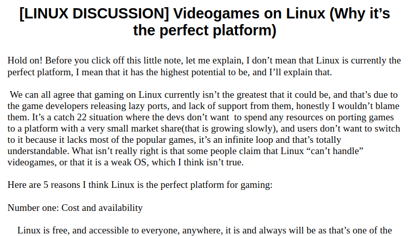
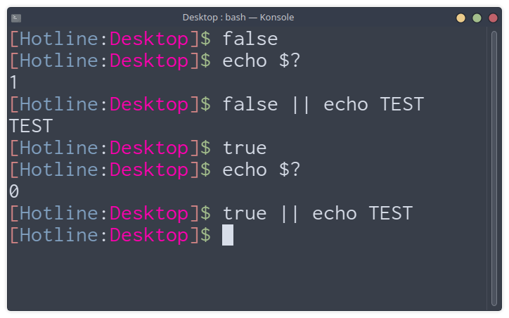
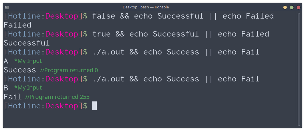
As you can see, it was more of a note that was supposed to start a discussion. Needless to say, I did not really know much about the tech industry at the time. I just had some hopes and dreams, a bit of technical knowledge, and the will to communicate them. In my defence, I was in high school, ha!</p>

<h2 id="satharuswordpresscom">satharus.wordpress.com</h2>
<p>At first, I started the blog on WordPress using the first template I could find. However, throughout the years and after many different iterations, themes, and names: Satharus’ not-so-secret diary, Satharus’ Blog, and finally, Blog of Satharus, I moved to GitHub Pages for a more reader-friendly experience with no forced tracking. At that point, I gave it the name “Technoir”. This is the current version of “Technoir - Blog of Satharus” which I plan on keeping.</p>

<p class="info">A small piece of trivia, “Satharus” was the name of my character in a couple of RPG games during high school and it just kinda stuck with me. It doesn’t mean anything and I literally got it from a random name generator in World of Warcraft.</p>

<h1 id="but-why">But, why?</h1>
<p>Why not? It is fun.</p>

<p style="text-align:center"><img src="https://media.tenor.com/H3KstxjGl6YAAAAC/i-liked-it-i-was-good-at-it.gif" alt="" /></p>

<h4 id="in-all-seriousness-though-i-started-this-blog-and-continue-to-write-for-many-reasons">In all seriousness, though, I started this blog and continue to write for many reasons:</h4>
<h2 id="knowledge-sharing">Knowledge Sharing</h2>
<p>
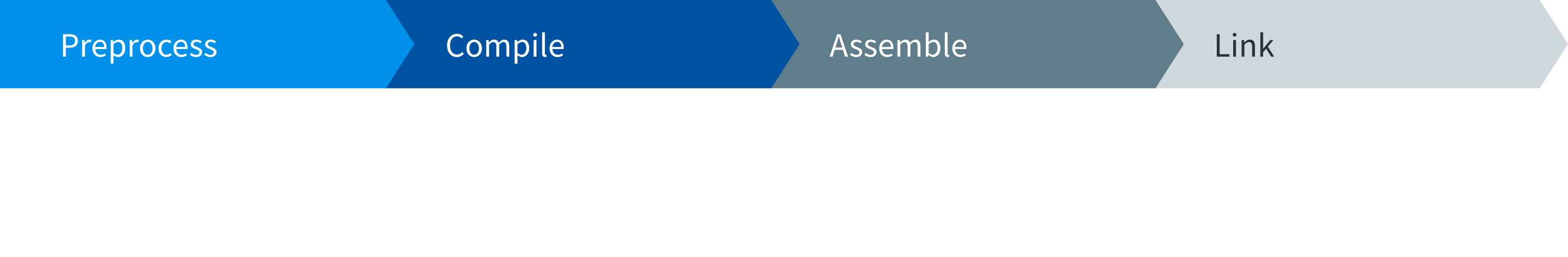
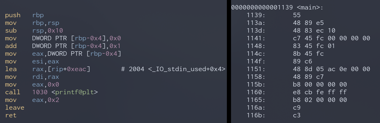
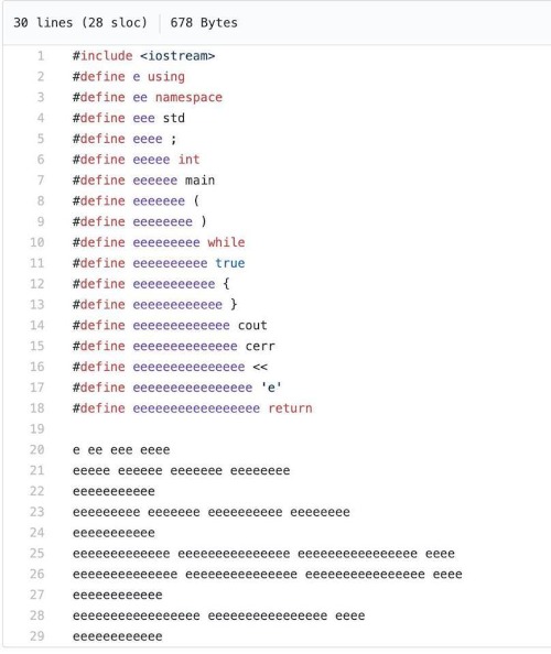
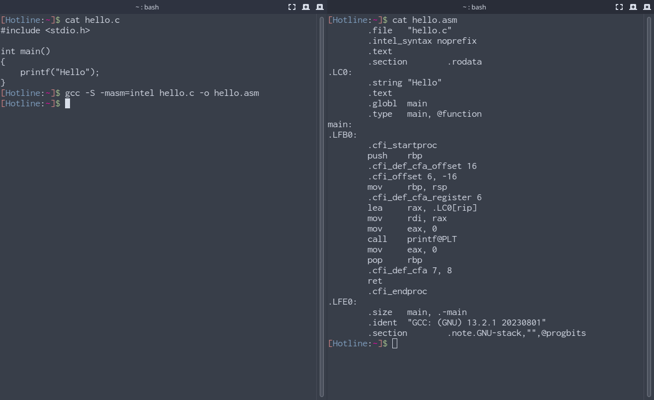
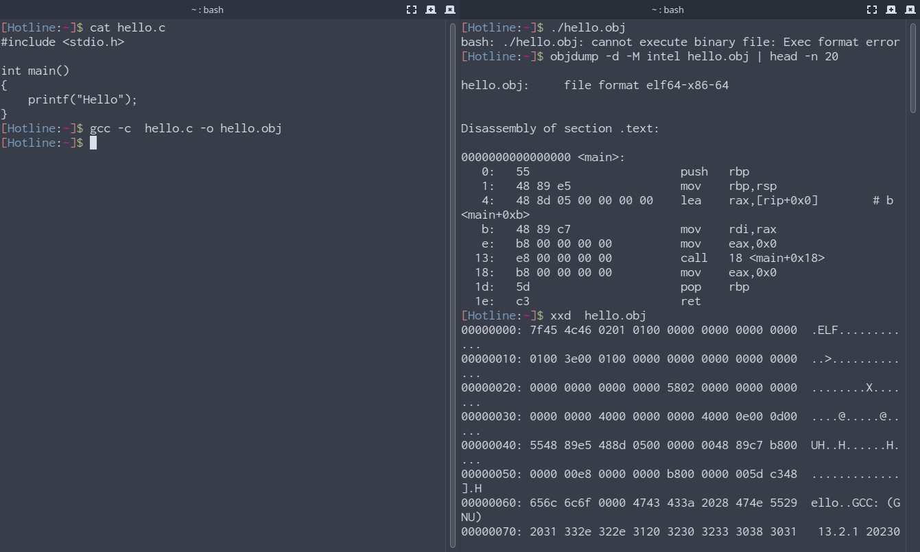
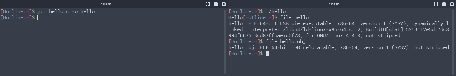
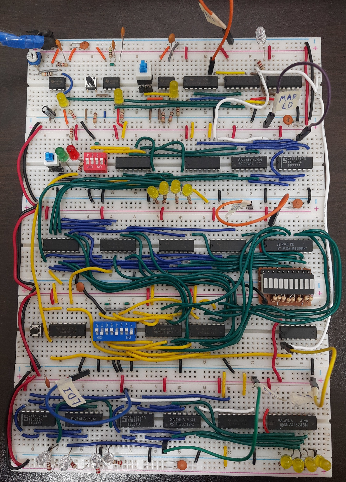
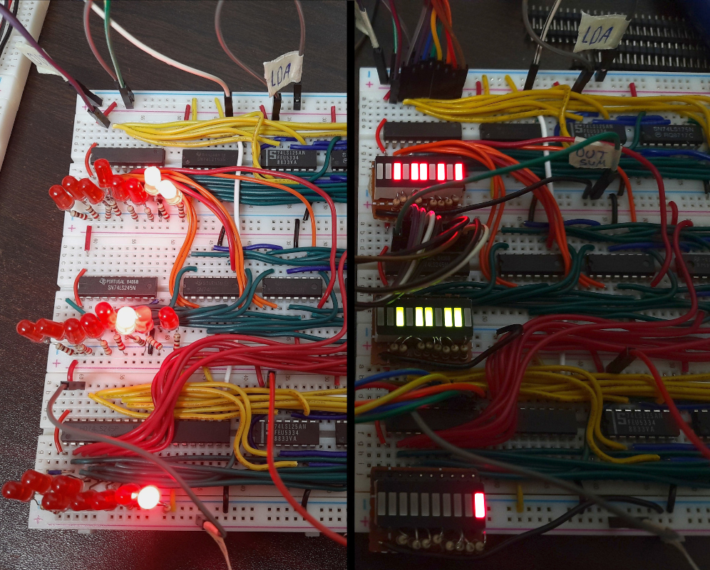
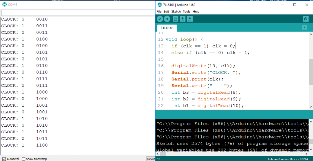
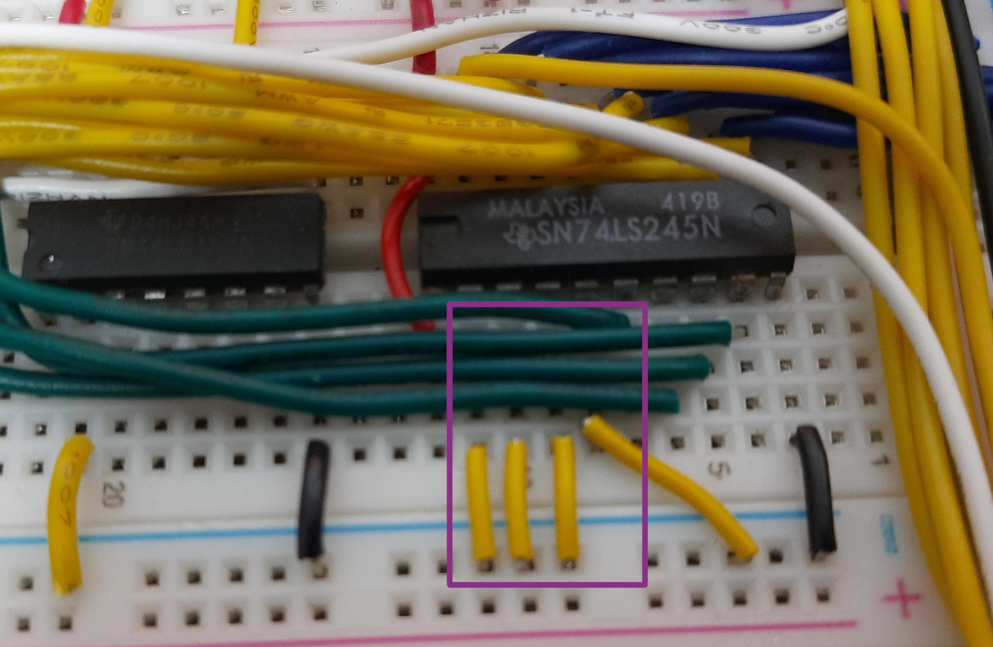
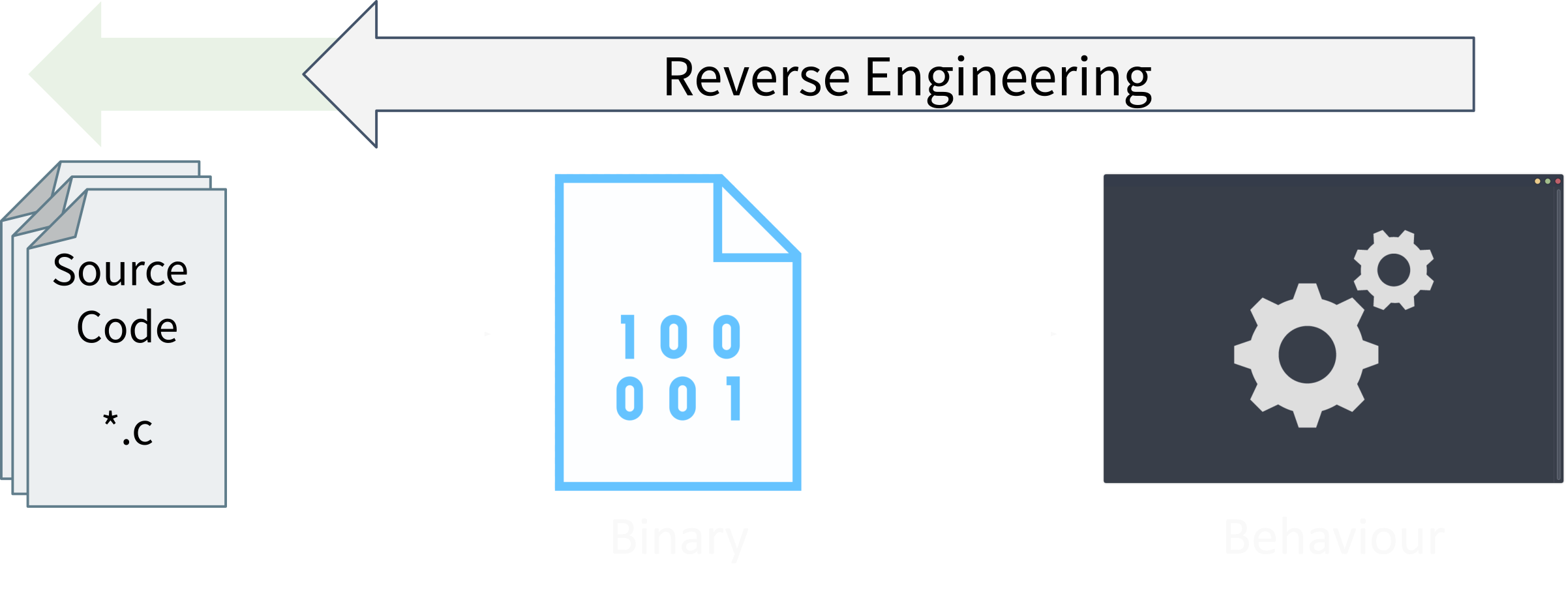
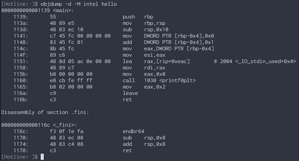
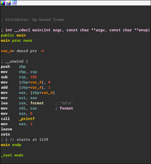
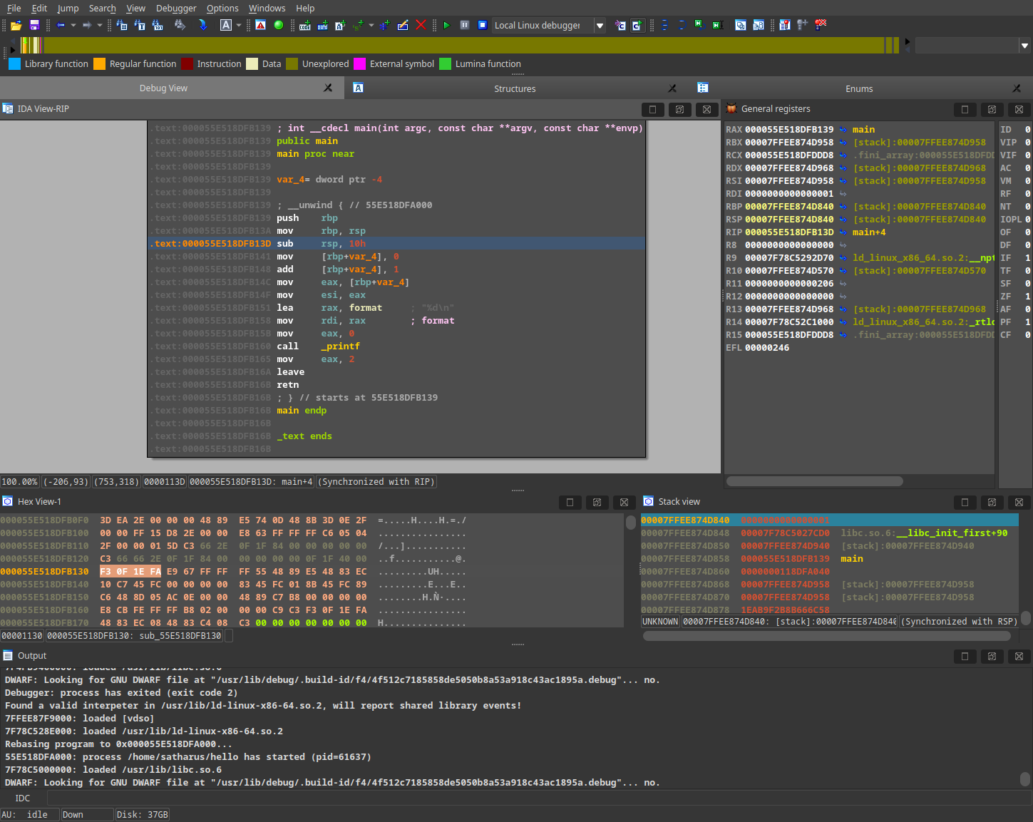
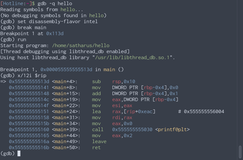
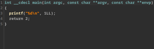
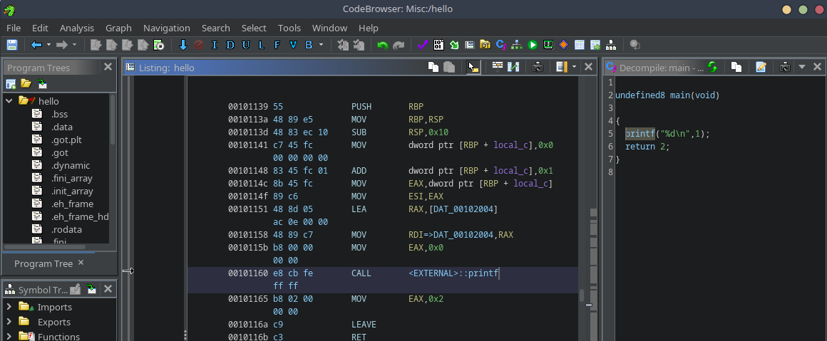
This blog started as, and still is, a way for me to share any knowledge or ideas I have with the community. Sometimes it was purely a guide such as <a href="/tech/2019/10/06/masm_linux.html">using MASM on Linux</a> or <a href="/cybersecurity/2019/12/02/the_art_of_cybersecurity.html">getting started with cybersecurity</a>. Sometimes it would be a tutorial or an educational piece such as <a href="/cybersecurity/2021/05/10/powershell_deobfuscation.html">PowerShell deobfuscation</a>, <a href="/cybersecurity/2023/03/28/edr_tests.html">adversary emulation through EDR tests</a>, or <a href="/archive.html?tag=Reverse+Engineering">reverse engineering</a>. Other times, it was a series on a specific topic such as the <a href="/archive.html?tag=8Bit+Computer">8Bit computer build</a> or <a href="/archive.html?tag=Buffer+Overflows">buffer overflows</a>. A couple of times, it was just pure banter, whether about <a href="/tech/2018/12/12/beauty_of_open_source.html">open source</a>, <a href="/misc/2019/07/11/optimistic_nihlism.html">the meaning of life</a>, or how <a href="/tech/2022/05/08/there_is_no_single_roadmap.html">there isn’t a specific roadmap for success</a>. And many, <a href="/archive.html">many more topics</a>.</p>

<p>This blog became a canvas for me to share anything and everything I wanted to share.</p>
<h2 id="experimentation">Experimentation</h2>
<p>
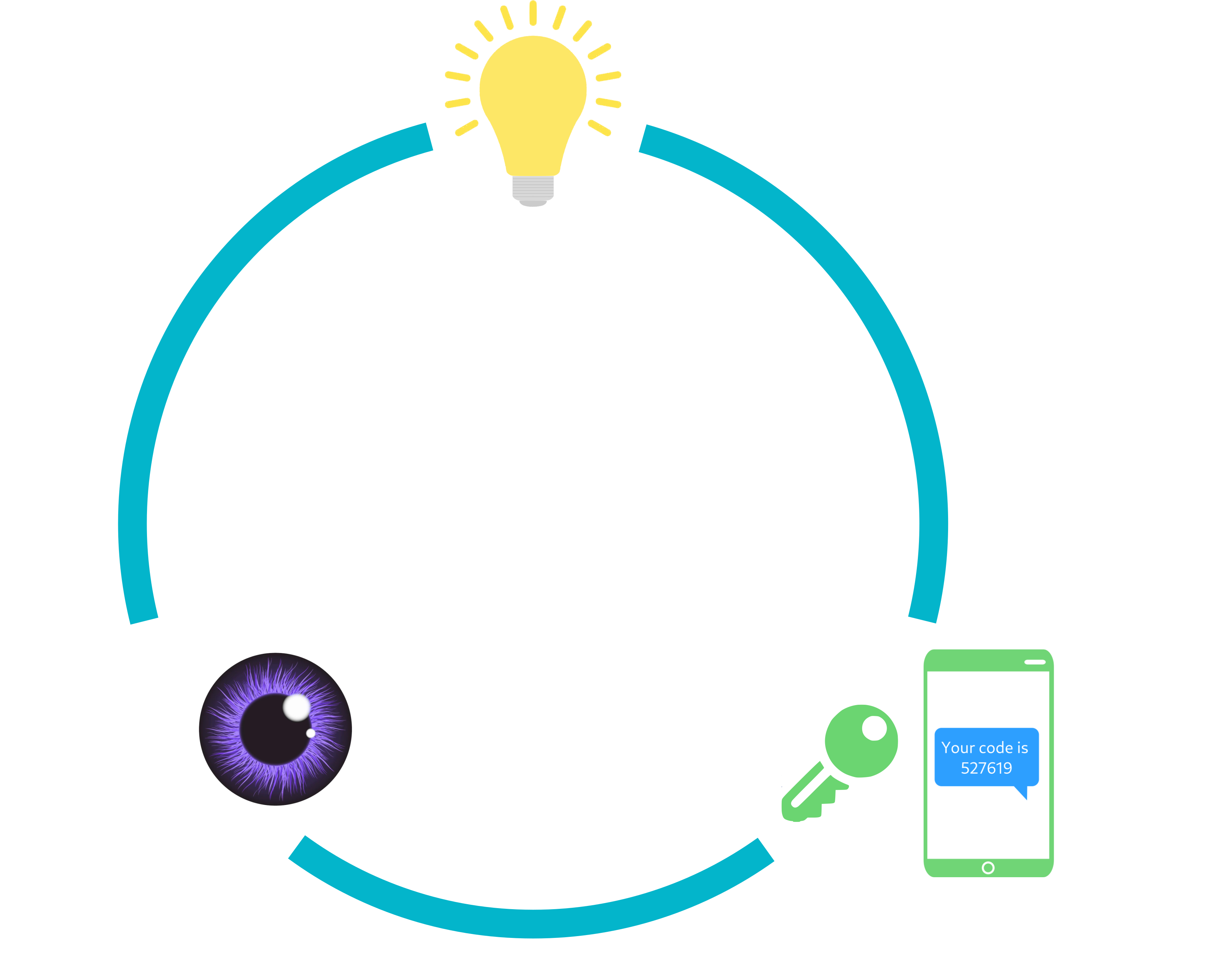
I love tinkering. I love messing around with everything and getting to know how things work. This blog gave me a chance to experiment and share my experiments with the world. Such as that time I thought of a fresh <a href="/cybersecurity/2022/08/17/sysmon-eid-27-bypass.html">bypass for a newly-released Sysmon event</a>. While the bypass itself is simple (and doesn’t require a blog), it connected me with many like-minded individuals with similar interests online which helped me connect more with the community and see what people at the time thought of the new Sysmon release, red-teaming strategies, and many other interesting topics. It also opened the door for me to experiment more with how Sysmon works.</p>

<h2 id="joy-of-writing">Joy of Writing</h2>
<p>Writing is fun. Or at least, in my opinion. This blog has been a side hobby for me over the years and has helped me relax many times by just writing whatever I wanted to. With the exception of 2023, I never had any pressure from myself to write regularly here. I only wrote when I felt like it. Therefore, there was no stress factor.</p>

<h1 id="what-did-i-gain">What Did I Gain?</h1>
<h2 id="knowledge">Knowledge</h2>
<p>I learnt. A lot. I learnt many things, whether while researching topic ideas, writing about topics I already knew a fair share about, researching topics I <em>somewhat</em> knew, or having a reader message me or comment a fun fact regarding a topic I wrote. I learnt from all of these. More importantly, I learnt more about writing and improved my communication skills and consistency.</p>

<h2 id="friends">Friends!</h2>
<p>While this blog started originally for my inner circle and friends, I think it went beyond that and at the same time connected me with many other professionals and new friends. I got to know so many like-minded people.</p>

<h2 id="impact-on-the-community">Impact on the Community</h2>
<p>It is always nice to give back. I feel that this blog, in one way or another, has given back to the community. You have no idea how happy it makes me when someone reaches out for advice or a question based on something they read on this blog. It does make me feel like I have truly given back to the community.</p>

<p>Giving back to the community matters because without the community, public resources, and knowledge sharing, you <em>probably</em> wouldn’t be where you are now. It is nice to be proud of yourself, your effort, dedication, and work, but in the end, you still have to remember those who have helped you (even indirectly), be grateful to them, and give back when you can. If you believe that you’ve succeeded completely through your own hard work and research, I have bad news for you. :)</p>

<h2 id="commitment-partially">Commitment (partially)</h2>
<p>“The exception of 2023”… Well, this year, as you can see, I have published a blog post every month. While it may not have been easy for me to think of different ideas to write about, I managed to do it.</p>

<p>However, in previous years, I sometimes committed myself to getting a blog post out “in time” for a specific event or date. Overall, I saw a slight increase in my commitment skills 😃. This blog was, and still is, a way for me to commit to writing ideas I have.</p>

<h2 id="people-liked-it">People Liked It!</h2>
<p>This blog has been acknowledged by many people in the industry. This helped me get myself out there. No one can deny that it is good for your career!</p>

<p>Management at previous jobs have acknowledged my writing skills by reading my blog and allowed me to write for the company’s blog even though it wasn’t my job to write at the time at all. One of the side duties I had at some point was advising the presales and marketing teams technically by helping them write. This gave me exposure to other parts of the industry which I had no idea about.</p>

<p>Recruiters have also read my blog and some have commented about it in my interviews over the years. This is obviously because I have it on my resume. However, if they wanted to reach it other ways they probably could.</p>

<h1 id="get-yourself-out-there">Get Yourself Out There!</h1>
<p>If you have any ideas or knowledge you want to share, create a blog, and post the ideas there! There are many platforms you can blog on. This includes <a href="https://substack.com">Substack</a>, <a href="https://medium.com">Medium</a>, <a href="https://dev.to">Dev</a>, or even <a href="https://www.linkedin.com/article/new/">LinkedIn Articles</a>. Use whatever makes you get your ideas out there. You don’t have to know web development or create your website from scratch. Just get blogging! There is no reason to hesitate about it. Get your ideas out there and don’t let any fears hold you back. There is no such thing as a bad idea.</p>

<h1 id="epilogue">Epilogue</h1>
<p>It has been five years of maintaining this blog, and I don’t mean to stop any time soon.<sup>(just pls don’t expect a blog each month next year as well thx)</sup></p>

<p>Thanks for sticking throughout the journey! Here’s to five years of creativity, knowledge sharing, joy, and success 🍻. Obviously, none of this would’ve existed without any of you, my readers. Those who follow the blog, give feedback, and share it with their friends are the reason I continue doing this!</p>

<p>
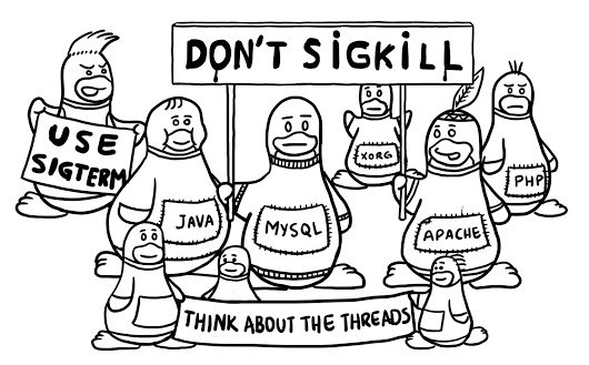
Since it started with comic books, to finish this reflection, I will share one of my favourite comic strips. Here’s to anyone who ever felt that whatever they’re doing isn’t enough or doing an impact.
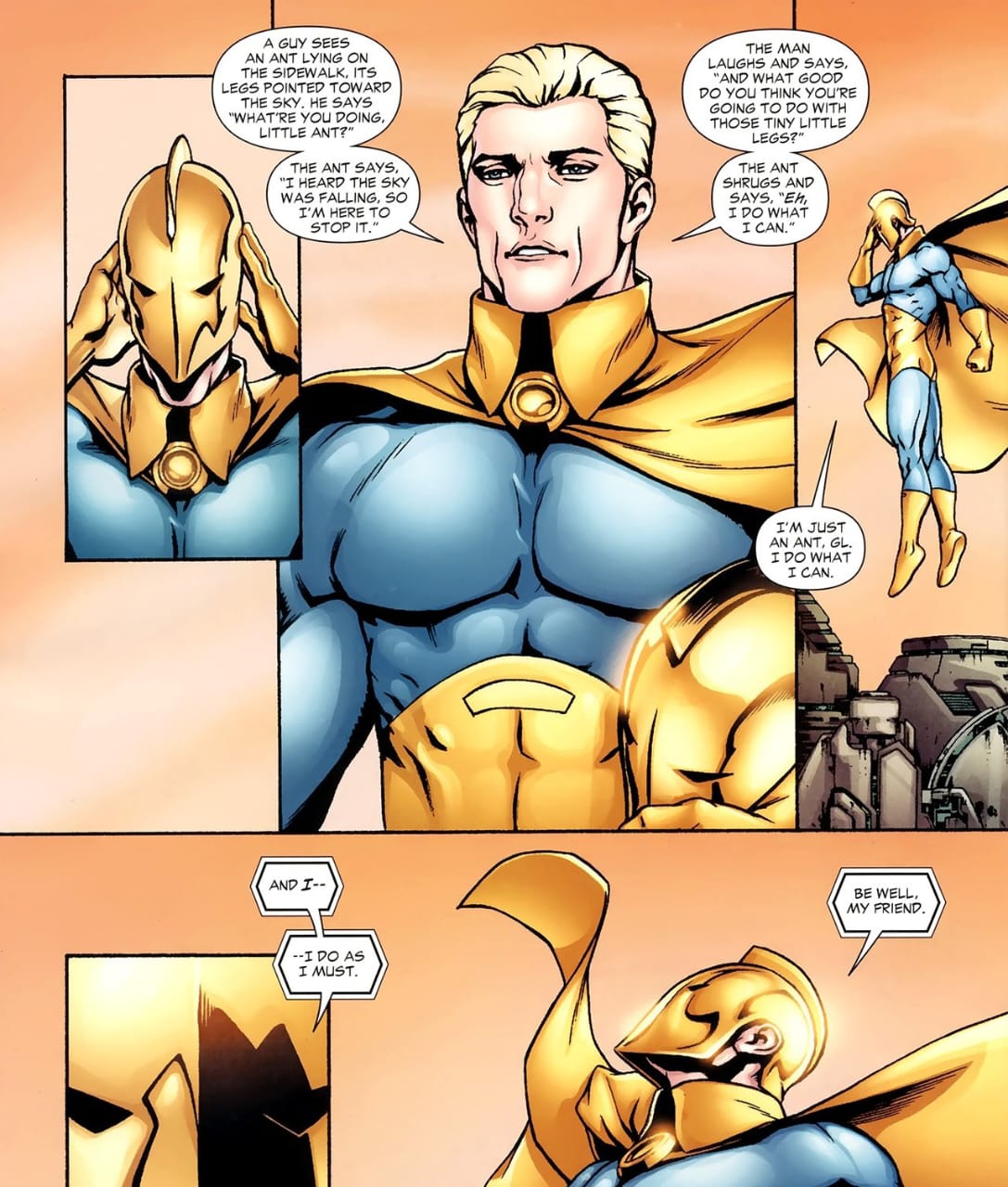
</p>

<p style="text-align:center"><img src="/assets/images/5-anniversary/BraveAndTheBold.jpeg" alt="Brave and the bold comic strip" /></p>

<p style="text-align:center"><a href="https://dc.fandom.com/wiki/The_Brave_and_the_Bold_Vol_3">The Brave and The Bold Volume 3</a> <a href="https://dc.fandom.com/wiki/The_Brave_and_the_Bold_Vol_3_30">#30</a>, DC Comics (Feb 2010)</p>

<p>Until next time, dear reader. As always, thanks for reading.</p>

<p>Cover image credit: <a href="https://www.reddit.com/r/PHONEHOM/comments/co292r/everyone_on_the_beach/">Everyone on the beach</a> by <a href="https://www.reddit.com/user/RetroFreak05/">/u/RetroFreak05</a></p>]]></content><author><name>Ahmed Elmayyah</name></author><category term="Misc" /><category term="Life" /><category term="Career" /><summary type="html"><![CDATA[Five years. Five whole years. So many things have changed since I first started this blog. I was still in my second year of university, no one could have even imagined that COVID-19 would happen, the GDPR had just been freshly implemented, and we were all looking forward to the end of the 2010s as we were approaching a new decade. Don’t we all just love how that went? The first blog post I ever posted here was on 7 Dec. 2018. However, my story with writing goes way beyond that. If you’re not interested in the story, you can skip to “But, why?”. In the other half of this post, I talk about why I started this blog, what I gained from it, and why you may want to do the same.]]></summary></entry><entry><title type="html">Decoding Circuits: Hardware Reverse Engineering</title><link href="https://satharus.me/tech/2023/11/30/hardware_reverse_engineering.html" rel="alternate" type="text/html" title="Decoding Circuits: Hardware Reverse Engineering" /><published>2023-11-30T00:00:00+02:00</published><updated>2023-11-30T00:00:00+02:00</updated><id>https://satharus.me/tech/2023/11/30/hardware_reverse_engineering</id><content type="html" xml:base="https://satharus.me/tech/2023/11/30/hardware_reverse_engineering.html"><![CDATA[<p>In a previous blog post, I mentioned that hardware can be reverse-engineered. But, why? And how? Is it legal? We shall embark on a journey today to reverse engineer an Arduino Uno R3 ethically and legally, guiding you through how it is done.</p>

<!--more-->

<p class="info">This post is an introduction to hardware reverse engineering. There are many more advanced techniques and ways to reverse engineer boards which I won’t get into this time.</p>

<h5 id="but-wait-isnt-arduino-open-source">But, wait, isn’t Arduino open-source?</h5>
<p>Well, yes. The Arduino Uno R3 is an open-source microcontroller board, but we’ll treat it as a black box. Legally (and I’ll touch on this later), reverse engineering an open-source project is the safest choice for us. We’ll ignore Arduino’s public schematic for now. However, if you decide to give reversing this entire board a try, you can compare your output to the original schematic!</p>

<p style="text-align:center"><img src="/assets/images/hardware-reverse-engineering/20231112_214359.jpg" alt="" /></p>

<h1 id="ethics-and-legality-of-reverse-engineering">Ethics and Legality of Reverse Engineering</h1>
<p>Please be careful. Before doing any type of reverse engineering, make sure it’s ethical and legal to do so where you live. Read the <a href="https://www.eff.org/issues/coders/reverse-engineering-faq">Electronic Frontier Foundation’s Reverse Engineering FAQs</a> for a US perspective on the legality and ethics of reverse engineering. While there is a lot of open-source or public-domain software which you can safely and legally reverse engineer, I can’t say the same about hardware. You can check the <a href="https://en.wikipedia.org/wiki/List_of_open-source_hardware_projects">list of open-source hardware projects on Wikipedia</a> and maybe you’ll find something you like there.</p>

<p class="warning">I am not a lawyer, so don’t take anything I say here as any form of legal advice.</p>

<p>Now that we have our legal bits figured out, let’s get started!</p>

<h1 id="step-0-disassembly">Step 0: Disassembly</h1>
<p>This is a prerequisite which we won’t really get into because it isn’t really in our scope. Also, the Arduino board we’re working with doesn’t need disassembly as the board is already exposed.</p>

<p>The only tip I’d give for this stage is to try and find a teardown or disassembly guide for the device you’re trying to reverse engineer, or a similar one.</p>
<h1 id="step-1-identifying-components">Step 1: Identifying Components</h1>
<p>The first step in reverse engineering hardware is identifying the components on the board.</p>
<h2 id="chip-markings">Chip Markings</h2>
<p>Most of the time, there are markings on the chips which are soldered to/placed on the board. These markings usually indicate exactly what a chip is or are some sort of code that you’d have to look up to know what that component is, or what its value is. For example, a chip may have its exact part number on it. A resistor, on the other hand, will usually have either a number on it or colour bands which indicate the resistance value.</p>

<p style="text-align:center"><img src="/assets/images/hardware-reverse-engineering/Resistor.png" alt="" /></p>

<p style="text-align:center">An example of how resistor values are read</p>

<h2 id="identifying-the-main-components">Identifying the Main Components</h2>
<p>“Main” will differ depending on what your goal is with reverse engineering. However, what I mean by “main” here is the parts that stand out and could be quite easy to read the markings on. For example, on this Arduino board, we can see a huge Atmel chip with very clear markings. The chip in this case, especially with the number of pins it has, could be a good place to start.</p>

<p>This isn’t always the case, and the size of the chip doesn’t have anything to do with how important it is. However, as an example, it can just give us a starting point.</p>

<p>So, let’s do just that! Let’s identify the “main” components.</p>

<p style="text-align:center"><img src="/assets/images/hardware-reverse-engineering/Components_numbered.jpg" alt="" /></p>

<p class="info">PSA: You may not need a fancy camera, microscope, or high-end phone for this kind of reverse engineering. Depending on your case, you could most likely get by by using the macro lens (or a high zoom in good lighting) on your smartphone. These adequate photos here were taken on an over 3-year-old Samsung Galaxy M31 using the default macro camera mode.</p>

<p>That’s a fair share of components. Where do we begin? It would be a good idea to start with whatever you’re familiar with. But, don’t fret, if you’re not familiar with any of them, let’s get to a search engine!</p>
<h3 id="my-first-component">My First Component</h3>
<p>Let’s start with component #1. Assuming that I have no idea what that is, what do I do? Look up whatever is on it. You literally don’t even have to think about it. Just type in whatever you see!</p>

<p style="text-align:center"><img src="/assets/images/hardware-reverse-engineering/Search.png" alt="" /></p>

<p>Clicking on the first link takes us to the datasheet of a <a href="https://www.ti.com/lit/ds/symlink/lm1117.pdf">Low-Dropout Linear Voltage Regulator</a>. Upon inspecting the datasheet, it seems like we have the 5-volt output variant and we can find the pin configuration for it as well.</p>

<p style="text-align:center"><img src="/assets/images/hardware-reverse-engineering/Package1117.png" alt="" /></p>

<p>Congrats! Now we know our first component and what its pins are. We can do the same thing for all of the remaining components to try and identify what they are.</p>
<h3 id="component-list">Component List</h3>
<p>Following the exact same steps as above, we can identify each component. Right now, it doesn’t matter why each component is in the circuit. All that we care about is that we identify what each component is, which will lead to us understanding what it does, and (hopefully) why it is on this board. Some components are easier than others to identify and find. Let’s take a look at the detective work required! 🕵️</p>

<h4 id="can-i-reverse-engineer-daddy"><em>Can I reverse engineer, Daddy?</em></h4>

<p style="text-align:center"><img src="/assets/images/hardware-reverse-engineering/1-Easy.png" alt="" /></p>

<h5 id="component-1---1117-voltage-regulator">Component #1 - 1117 Voltage Regulator</h5>
<p>This one we already identified. <a href="https://www.ti.com/lit/ds/symlink/lm1117.pdf">Datasheet here</a>.</p>
<h5 id="component-2---sgm8542-operational-amplifier">Component #2 - SGM8542 Operational Amplifier</h5>
<p>A simple search leads to the <a href="https://www.sg-micro.com/uploads/soft/20230731/1690789373.pdf">datasheet here</a>.</p>
<h5 id="component-4---47μf-25v-electrolytic-capacitor">Component #4 - 47μF 25V Electrolytic Capacitor</h5>
<p>Looking up “CS 47 25V” leads us to <a href="https://www.futurlec.com/Capacitors/C047U25ESMD.shtml">this page</a> which tells us that it is, to come as no surprise, a 47μF 25V electrolytic capacitor.</p>
<h5 id="component-5---m7-general-purpose-dioderectifier">Component #5 - M7 General Purpose Diode/Rectifier</h5>
<p>Again, looking up “M7 SMD” leads us to many results which tell us about a series of diodes M1 through M7 with varying reverse voltages. <a href="https://datasheet.lcsc.com/lcsc/1912111437_Yangzhou-Yangjie-Elec-Tech-M7_C211752.pdf">This page</a> has more info on them.</p>

<p class="info">A Surface-Mount Device (SMD) is one that is mounted on the surface of the PCB itself and not through a hole in the PCB. SMDs are usually smaller and allow for a higher component density on the PCB. You’ll know an SMD when you see one!</p>

<h5 id="component-8---atmega328p-microcontroller">Component #8 - ATmega328P Microcontroller</h5>
<p>The centrepiece of this board. The main microcontroller. Just by looking up the chip marking, we can reach the <a href="https://www.microchip.com/en-us/product/atmega328p">product page here</a> and from the datasheets, we can find its pin diagram as well.</p>
<h5 id="component-9---atmel-mega16u2">Component #9 - Atmel MEGA16U2</h5>
<p>Just like component #8, we can just look up the chip marking and find ourselves on the <a href="https://www.microchip.com/en-us/product/atmega16u2">product page</a> which contains the <a href="https://ww1.microchip.com/downloads/aemDocuments/documents/OTH/ProductDocuments/DataSheets/7799S.pdf">summary datasheet</a>. This datasheet tells us that this is a microcontroller with a “USB 2.0 Full-speed Device Module”. The fact that it looks like it is connected to the USB Type-B port suggests that it could be the USB controller.</p>

<h4 id="please-guide-me"><em>Please guide me</em></h4>

<p style="text-align:center"><img src="/assets/images/hardware-reverse-engineering/2-Moderate.png" alt="" /></p>

<h5 id="component-3---10kω-smd-resistor-network">Component #3 - 10KΩ SMD Resistor Network</h5>
<p>Looking up “103 SMD” leads us to some results which look similar. But, not quite exactly. Looking up “103 SMD 8 pins” leads us to learn that this is an SMD resistor network array of 10×10<sup>3</sup> = 10KΩ.</p>
<h5 id="component-11---22ω-smd-resistor-network">Component #11 - 22Ω SMD Resistor Network</h5>
<p>The same can be done for component #12, which is a 22×10<sup>0</sup> = 22Ω.</p>
<h5 id="component-10---16mhz-crystal-oscillator">Component #10 - 16MHz Crystal Oscillator</h5>
<p>Again, this is much easier if you know what a crystal looks like. Otherwise, you could look up “T16.000” which will eventually lead you to find out that it is a 16MHz crystal oscillator.</p>
<h4 id="bring-em-on"><em>Bring ‘em on!</em></h4>

<p style="text-align:center"><img src="/assets/images/hardware-reverse-engineering/3-Hard.png" alt="" /></p>

<h5 id="component-7---self-resetting-smd-fuse">Component #7 - Self-resetting SMD Fuse</h5>
<p>This could be hard to search without somewhat knowing what to look for. I know what this is because it is one of the ways to tell if an Arduino is counterfeit or not. According to <a href="https://support.arduino.cc/hc/en-us/articles/360020652100-How-to-spot-a-counterfeit-Arduino">this article</a>, you can see that they have a custom design for a golden-black SMD fuse. However, most SMD fuses don’t look that different. If you know what an SMD fuse looks like, you’ll probably guess this. If not, then you may be able to figure it out later. Either from the context of the connections or by digging deep enough on the internet.</p>

<p style="text-align:center"><img src="/assets/images/hardware-reverse-engineering/Counterfeit.png" alt="" /></p>

<h4 id="i-am-chips-incarnate"><em>I am Chips incarnate!</em></h4>

<p style="text-align:center"><img src="/assets/images/hardware-reverse-engineering/4-Brutal.png" alt="" /></p>

<h5 id="component-6---g2l-smd-component">Component #6 - G2L SMD Component</h5>
<p>“G2L SMD” leads us to <a href="https://www.aliexpress.com/item/32295366358.html">this page</a>, a Chinese online shopping platform, which states that it is a small outline transistor with 5 leads/pins (SOT23-5). This is a little bit misleading, as we can also find <a href="https://www.taobao.com/list/item/684769162720.htm">this page on Taobao</a> which states that it is a linear voltage regulator in a SOT23-5 package. We could figure that out later at some point. For now, we have sort of an idea of what it is.</p>

<p class="info">Side protip: You can use GIMP, Photoshop, Paint, or any other similar program to label chips and traces</p>

<h1 id="step-2-trace-trace-trace">Step 2: Trace, Trace, Trace!</h1>
<p>Now that we know what each component is, it is time to figure out how they’re connected. There are multiple techniques you can use to figure this out. Let’s look at some examples.</p>

<p style="text-align:center"><img src="/assets/images/hardware-reverse-engineering/Two_Points.jpg" alt="" /></p>

<p>One of the easy things you can do is trace the connections with your eyes. You will get varying accuracy with this method, depending on how visible the traces are and if the PCB has multiple layers or not. In the image above, we can see that the two labelled pints seem to be connected.</p>

<p>To confirm our connection hypothesis, we can test if the traces are connected with a multimeter. Most multimeters have a <a href="https://www.fluke.com/en-gb/learn/blog/digital-multimeters/how-to-test-for-continuity">continuity test mode</a>, where you can use the leads to test if two points in a circuit are connected.</p>

<p style="text-align:center"><img src="/assets/images/hardware-reverse-engineering/Multimeter.jpg" alt="" /></p>

<p style="text-align:center">The multimeter is set to test continuity (green box) and the two points are connected (red line)</p>

<p>Indeed, when we test for continuity, we get a buzzing sound from the multimeter which indicates that these two points are connected. What are these, though? Well, these two points are both solder joints. We’d have to flip the board to see which components are soldered at which location. If you’re unsure, just use the multimeter!</p>

<p style="text-align:center"><img src="/assets/images/hardware-reverse-engineering/Two_Points_Top.jpg" alt="" /></p>

<p>Cross-referencing the datasheet with the pins we found, we can see that pin 13 (PD7) of the ATmega328P is connected directly to the female header labelled “7” which is pin 7 of the Arduino. We can safely assume that the Arduino uses PD7 directly as a digital port. We can tell which way the chip is placed based on the notch (marked in yellow in the picture).</p>

<p>Now all we have to do is do the same for each chip or component on this board, and see where it is connected.</p>
<ul>
  <li>A) Select a chip or component on the board</li>
  <li>B) Trace where its connections are going</li>
  <li>C) Check the datasheet to see what the functionality or names of the pins are
    <ul>
      <li>This is just to be able to refer to them later as we analyse the circuit a bit further</li>
    </ul>
  </li>
  <li>D) Rinse and repeat</li>
</ul>

<p>To keep track of it all, you can use electronic design automation (EDA) software like <a href="https://easyeda.com/">EasyEDA</a>, <a href="https://www.kicad.org/">KiCad</a>, <a href="https://www.autodesk.com/products/eagle/overview">EAGLE</a>, <a href="https://www.labcenter.com/">Proteus</a>, or use pen and paper (the more colourful the better!). Whatever you find easy, can afford, and can obtain legally. Some EDA software is available for students at discounts or even free.</p>

<h1 id="step-3-understand-or-guess-the-connections">Step 3: Understand (or Guess) the Connections</h1>
<p>You can do this step simultaneously with the previous step (i.e. figure out the functionality of each chip on its own, referring to its datasheet), or you can start checking the datasheets after you’ve traced all the connections.</p>

<p>Let’s for example figure out some of the pins of the ATmega328P and what their functions are on this board.</p>

<p style="text-align:center"><img src="/assets/images/hardware-reverse-engineering/Traces.jpg" alt="" /></p>

<p>Just by tracing from the pictures we took, we can see that there are some pins on the ATmega chip which are connected to Arduino’s digital pins, just like the previous example. However, when there is a via, the pictures weren’t enough. The yellow, orange, and off-white traces in the picture above are coming out from the Arduino pins into a via. If we flip the board (top right image), we can see the traces coming out of the vias into the ATmega chip. Even though this isn’t really visible to us due to the traces going under components already in place, we can verify it with our trusty multimeter and test to see where the trace coming out of the via goes!</p>

<p class="info">A via is a connection between two or more layers of a PCB. It’s usually a drilled hole and you’ll see a trace on one side terminate at the via and another on the other side start from it (or vice-versa!).</p>

<p style="text-align:center"><img src="/assets/images/hardware-reverse-engineering/Crystal.jpg" alt="" /></p>

<p>A seemingly small part that stands out is this silver thing connected between two of the ATmega’s pins. We have no idea what that component is and it doesn’t seem to have a very clear marking. However, using our multimeter and by looking at the traces, we can tell that they connect the silver components to pins <code class="language-plaintext highlighter-rouge">PB6</code> and <code class="language-plaintext highlighter-rouge">PB7</code> of the ATmega chip.</p>

<h2 id="to-the-datasheet">To the Datasheet!</h2>
<p>Looking at the pinout diagram from the datasheet, we can see that digital pins 0 through 11 (as well as 12 and 13, trust me!) are connected to what seem like I/O ports on the ATmega328P. Arduino pin 0 is connected to ATmega <code class="language-plaintext highlighter-rouge">PD0</code>, pin 1 to <code class="language-plaintext highlighter-rouge">PD1</code>, pin 2, to <code class="language-plaintext highlighter-rouge">PD2</code>, and so on. All the way until pin 8, which is actually connected to <code class="language-plaintext highlighter-rouge">PB0</code>, and then pin 9 is connected to <code class="language-plaintext highlighter-rouge">PB1</code>, and so on until we reach pin 13 which is connected to <code class="language-plaintext highlighter-rouge">PB5</code>.</p>

<p>But, what do these pins on the ATmega actually do?  If we check the datasheet, we can find their exact descriptions.</p>

<p style="text-align:center"><img src="/assets/images/hardware-reverse-engineering/Ports.jpg" alt="" /></p>

<p>They’re both 8-bit bi-directional I/O ports. Cool! Now we know why they’re connected to Arduino’s digital pins. But, wait a minute… What about <code class="language-plaintext highlighter-rouge">PB6</code> and <code class="language-plaintext highlighter-rouge">PB7</code>?</p>

<p>We can see under 1.1.3. Port B - PB6 and PB7 can be connected to a crystal oscillator. We now know what that silver component is :)!</p>

<h2 id="multi-layer-pcbs">Multi-layer PCBs</h2>
<p>Since we mentioned vias, it is worth mentioning that not all boards are double-layer PCBs like this Arduino here. Many boards have way more than two, especially more complex ones. So, “the other side”, can be just a different layer that isn’t the outer one on either side. Depending on the design, you may find only the power traces in the outer layers and all of the data traces in the middle. In that case, it’ll require a bit more work :) For now, we’ll stick to our simple double-layer Arduino board!</p>

<h1 id="step-4-onwards">Step 4 Onwards</h1>
<p>At this point, you can do many things depending on what the goal of reverse engineering the hardware is. There are so many things you can do. It ranges from simply identifying the roles of the chips and drawing the schematic of the board, all the way to analysing what the electronic design of a chip on the board is internally. Let’s take a look at some of the things we can do.</p>

<h2 id="storageflash-dumping-and-analysis">Storage/Flash Dumping and Analysis</h2>
<p>If the board has a flash or a form of storage device on it, you could consider dumping it and analysing it. It could have important code, microcode, or anything which could hint at what the hardware is doing or help understand it better.</p>

<p>You can watch this video by <a href="https://twitter.com/ben_eater">Ben Eater</a> on analysing a ROM of an old TV censoring device! Super interesting.</p>

<div><div class="extensions extensions--video">
  <iframe src="https://www.youtube.com/embed/a6EWIh2D1NQ?rel=0&amp;showinfo=0" frameborder="0" scrolling="no" allowfullscreen=""></iframe>
</div>
</div>

<h2 id="test-pads-or-debug-headers">Test Pads or Debug Headers</h2>
<p>Some devices make it to the market with test pads or debug headers still connected and enabled on the board. These pads/headers are often used during development or for debugging. However, when they’re left by devs, whether accidentally or on purpose (for debugging or maintenance), they can be a very useful addition to analysis. You can use a logic analyser or an oscilloscope for this and see if you get anything useful. Here’s an example of <a href="https://datasheets.raspberrypi.com/rpizero2/raspberry-pi-zero-2-w-test-pads.pdf">test pad locations on a Raspberry Pi Zero 2 W</a>, another <a href="https://datasheets.raspberrypi.com/rpizero2/raspberry-pi-zero-2-w-reduced-schematics.pdf">open-source hardware project</a>.</p>

<h2 id="decapping-and-rtl-recovery">Decapping and RTL Recovery</h2>
<p>Another option to understand chips (especially those which don’t have a datasheet, weren’t documented, or are too old) is to decap them and look at them under a microscope. While that is probably expensive, it can yield some good results. If you don’t want to do it yourself, there are some services online which can do it. An example service is <a href="https://dirtypcbs.com/store/decap">DirtyPCBs’ Dirty Decapping</a>.</p>

<p>I’ve seen some people even X-ray chips and memory and analyse their content after digitally processing the images they got from the X-ray scans.</p>

<h1 id="and-then">And then?</h1>
<p>With enough time, patience, effort, and takeaway meals, we could reverse engineer the entire board and have an identical schematic for it just like the Arduino’s. However, this post is meant to be an introduction to hardware reverse engineering. Maybe, <em>just maybe</em>, sometime in the future we could do that :). For now, you know that hardware reversing exists and is just as fun as software reverse engineering!</p>

<p>Also, if hardware topics like this make you super curious and interested, you may want to check out <a href="https://nostarch.com/hardwarehacking">The Hardware Hacking Handbook by Colin O’Flynn and Jasper van Woudenberg</a>. Again, just please be careful. Only reverse engineer boards you are legally and ethically allowed to reverse engineer.</p>

<p>Thanks for reading! I hope this blog post was fun to read and was beneficial to you :) If you liked this post, please share it with your friends who take X-rays of flash chips for fun in their spare time!</p>

<p>Partial cover image credit: <a href="https://thenounproject.com/icon/digital-multimeter-5844411/">digital multimeter</a> by Good Father.</p>]]></content><author><name>Ahmed Elmayyah</name></author><category term="Tech" /><category term="Tech" /><category term="Reverse Engineering" /><category term="Low Level" /><category term="Hardware" /><summary type="html"><![CDATA[In a previous blog post, I mentioned that hardware can be reverse-engineered. But, why? And how? Is it legal? We shall embark on a journey today to reverse engineer an Arduino Uno R3 ethically and legally, guiding you through how it is done.]]></summary></entry><entry><title type="html">Back to Basics: Why do we return 0?</title><link href="https://satharus.me/tech/2023/10/27/exit_codes.html" rel="alternate" type="text/html" title="Back to Basics: Why do we return 0?" /><published>2023-10-27T00:00:00+02:00</published><updated>2023-10-27T00:00:00+02:00</updated><id>https://satharus.me/tech/2023/10/27/exit_codes</id><content type="html" xml:base="https://satharus.me/tech/2023/10/27/exit_codes.html"><![CDATA[<p>There is a very high chance that if you read my blog, you’ve seen the line of code <code class="language-plaintext highlighter-rouge">return 0;</code> at some point. Specifically, you’ve probably seen it in a <code class="language-plaintext highlighter-rouge">main()</code> function, like so:</p>

<div class="language-c highlighter-rouge"><div class="highlight"><pre class="highlight"><code><span class="kt">int</span> <span class="nf">main</span><span class="p">()</span>
<span class="p">{</span>
	<span class="c1">//Do stuff</span>
	<span class="k">return</span> <span class="mi">0</span><span class="p">;</span>
<span class="p">}</span>
</code></pre></div></div>

<p>Why, though? Can I return something that isn’t zero?</p>

<p>The simple answer is yes. <code class="language-plaintext highlighter-rouge">main()</code> is, after all, a function and can return whatever you want it to. Not just that, but programs in general can have <em>any</em> exit code.</p>

<h1 id="exit-codes">Exit Codes</h1>

<p>We have discussed before that when you run a program, the OS loads it as a <em>process</em>. That process executes instructions until it exits. However, before it exits, it sets an exit code(value) for the OS to tell it why or how it exited. Returning from the <code class="language-plaintext highlighter-rouge">main()</code> function makes the process terminate and sets the exit code to <code class="language-plaintext highlighter-rouge">main()</code>’s return value.</p>

<p style="text-align:center"><img src="/assets/images/exit-codes/return5.png" alt="" /></p>

<p class="info">On Linux, you can check the exit code of a process by using the shell variable <code class="language-plaintext highlighter-rouge">?</code>. On Windows, you can do the same by checking the variable <code class="language-plaintext highlighter-rouge">ERRORLEVEL</code>. e.g. <code class="language-plaintext highlighter-rouge">echo %ERRORLEVEL%</code>.</p>

<p>What if I want to exit the program from a function that isn’t <code class="language-plaintext highlighter-rouge">main()</code>?</p>

<h1 id="exit-system-call">Exit System Call</h1>
<p>You use an exit syscall. This differs between languages and OSs. However, Let’s look at Linux for an example.</p>

<p>On Linux, with the standard C library, you can call <a href="https://en.cppreference.com/w/c/program/exit"><code class="language-plaintext highlighter-rouge">void exit(int status)</code></a>. This will exit the process and set the exit code to <code class="language-plaintext highlighter-rouge">status</code> which is the parameter given to it.</p>

<p class="info">It is worth nothing that returning from the main function does eventually lead to an implicitly-called <code class="language-plaintext highlighter-rouge">exit()</code> as well.</p>

<h2 id="example">Example</h2>

<div class="language-c highlighter-rouge"><div class="highlight"><pre class="highlight"><code><span class="cp">#include</span> <span class="cpf">&lt;stdlib.h&gt;</span><span class="cp">
</span><span class="kt">void</span> <span class="nf">exitWithError</span><span class="p">()</span>
<span class="p">{</span>
	<span class="n">exit</span><span class="p">(</span><span class="mi">128</span><span class="p">);</span>
<span class="p">}</span>
<span class="kt">int</span> <span class="nf">main</span><span class="p">()</span>
<span class="p">{</span>
	<span class="n">exitWithError</span><span class="p">();</span>
	<span class="k">return</span> <span class="mi">0</span><span class="p">;</span>
<span class="p">}</span>
</code></pre></div></div>

<p style="text-align:center"><img src="/assets/images/exit-codes/exit128.png" alt="" /></p>

<h1 id="what-does-this-mean">What does this mean?</h1>
<p>Well, it is just a way of showing why or how a process terminated. Conventionally, <code class="language-plaintext highlighter-rouge">0</code> means “All good!”. The process executed fine and exited due to a normal reason (i.e. not a crash or error)<sup>[1]</sup>. Any other exit code would indicate some form of message regarding the process termination to the OS or user.</p>

<p><sup>[1]</sup> - That is if the developer programmed it <em>correctly</em>.</p>

<p class="info">On some modern operating systems(at least Linux), you’ll find exit codes to be ranging from <code class="language-plaintext highlighter-rouge">0</code> to <code class="language-plaintext highlighter-rouge">255</code>(an 8-bit integer value).</p>

<h2 id="example-use-case">Example Use Case</h2>

<p>If you’ve ever used a Debian-based Linux distro before, you may have seen someone tell you to run the command line: <code class="language-plaintext highlighter-rouge">sudo apt update &amp;&amp; sudo apt upgrade</code>. Have you ever asked yourself what <code class="language-plaintext highlighter-rouge">&amp;&amp;</code> does?</p>

<h3>&amp;&amp;</h3>

<p><code class="language-plaintext highlighter-rouge">&amp;&amp;</code> ensures that the previous “statement” (in this case, the execution of <code class="language-plaintext highlighter-rouge">apt update</code>) is true (i.e. exit status is <code class="language-plaintext highlighter-rouge">0</code>). There are two other useful Linux commands we can use to demonstrate this, which are <code class="language-plaintext highlighter-rouge">true</code> and <code class="language-plaintext highlighter-rouge">false</code> which return <code class="language-plaintext highlighter-rouge">0</code> and <code class="language-plaintext highlighter-rouge">1</code> respectively.</p>

<p style="text-align:center"><img src="/assets/images/exit-codes/truefalse.png" alt="" /></p>

<p>You can use this to only proceed if the previous command executed successfully. In the <code class="language-plaintext highlighter-rouge">apt</code> example, it wouldn’t upgrade the packages if there was an issue updating the package infromation.</p>

<h3 id="-1">||</h3>

<p>Even more interesting is <code class="language-plaintext highlighter-rouge">&amp;&amp;</code>’s evil sibling: <code class="language-plaintext highlighter-rouge">||</code>, which will proceed only if the previous command returned anything other than <code class="language-plaintext highlighter-rouge">0</code> (i.e. had a non-zero exit code).</p>

<p style="text-align:center"><img src="/assets/images/exit-codes/oror.png" alt="" /></p>

<h3 id="--and-exit-codes">||, &amp;&amp;, and Exit Codes</h3>

<p>Ultimately, we can use both in combination to do different things based on the success (or failure) of the process. We can use the following program to demonstrate that:</p>

<div class="language-c highlighter-rouge"><div class="highlight"><pre class="highlight"><code><span class="cp">#include</span> <span class="cpf">&lt;stdio.h&gt;</span><span class="cp">
</span><span class="kt">int</span> <span class="nf">main</span><span class="p">()</span>
<span class="p">{</span>
    <span class="kt">char</span> <span class="n">c</span> <span class="o">=</span> <span class="n">getchar</span><span class="p">();</span>
    <span class="k">if</span> <span class="p">(</span><span class="n">c</span> <span class="o">==</span> <span class="sc">'A'</span><span class="p">)</span>
        <span class="k">return</span> <span class="mi">0</span><span class="p">;</span>
    <span class="k">else</span>
        <span class="k">return</span> <span class="mi">255</span><span class="p">;</span>
<span class="p">}</span>
</code></pre></div></div>

<p style="text-align:center"><img src="/assets/images/exit-codes/example.png" alt="" /></p>

<p>You may or may not have asked yourself before why we return <code class="language-plaintext highlighter-rouge">0</code>. Whether you did or not, I hope you found this post useful, fun to read, or both!</p>

<h1 id="bonus">Bonus</h1>
<p>But, wait! There’s a bonus :) Remember when I said that <code class="language-plaintext highlighter-rouge">main()</code> is just a function and can return <em>whatever</em> you want? Can we make <code class="language-plaintext highlighter-rouge">main()</code> return <code class="language-plaintext highlighter-rouge">main()</code>? Pretty sure nothing can go wrong with that…</p>

<div class="language-c highlighter-rouge"><div class="highlight"><pre class="highlight"><code><span class="cp">#include</span> <span class="cpf">&lt;stdio.h&gt;</span><span class="cp">
</span>
<span class="kt">int</span> <span class="nf">main</span><span class="p">()</span>
<span class="p">{</span>
    <span class="n">printf</span><span class="p">(</span><span class="s">"Bad Recursion, Brb...</span><span class="se">\n</span><span class="s">"</span><span class="p">);</span>
    <span class="k">return</span> <span class="n">main</span><span class="p">();</span>
<span class="p">}</span>
</code></pre></div></div>

<p style="text-align:center"><img src="/assets/images/exit-codes/brb.gif" alt="" /></p>

<p>If you liked this post, please share it with your friends who like returning <code class="language-plaintext highlighter-rouge">-1</code> instead of <code class="language-plaintext highlighter-rouge">255</code>.</p>

<p>As always, thanks for reading.</p>]]></content><author><name>Ahmed Elmayyah</name></author><category term="Tech" /><category term="Tech" /><category term="Linux" /><category term="C" /><category term="Programming" /><summary type="html"><![CDATA[There is a very high chance that if you read my blog, you’ve seen the line of code return 0; at some point. Specifically, you’ve probably seen it in a main() function, like so: int main() { //Do stuff return 0; } Why, though? Can I return something that isn’t zero? The simple answer is yes. main() is, after all, a function and can return whatever you want it to. Not just that, but programs in general can have any exit code. Exit Codes We have discussed before that when you run a program, the OS loads it as a process. That process executes instructions until it exits. However, before it exits, it sets an exit code(value) for the OS to tell it why or how it exited. Returning from the main() function makes the process terminate and sets the exit code to main()’s return value. On Linux, you can check the exit code of a process by using the shell variable ?. On Windows, you can do the same by checking the variable ERRORLEVEL. e.g. echo %ERRORLEVEL%. What if I want to exit the program from a function that isn’t main()? Exit System Call You use an exit syscall. This differs between languages and OSs. However, Let’s look at Linux for an example. On Linux, with the standard C library, you can call void exit(int status). This will exit the process and set the exit code to status which is the parameter given to it. It is worth nothing that returning from the main function does eventually lead to an implicitly-called exit() as well. Example #include &lt;stdlib.h&gt; void exitWithError() { exit(128); } int main() { exitWithError(); return 0; } What does this mean? Well, it is just a way of showing why or how a process terminated. Conventionally, 0 means “All good!”. The process executed fine and exited due to a normal reason (i.e. not a crash or error)[1]. Any other exit code would indicate some form of message regarding the process termination to the OS or user. [1] - That is if the developer programmed it correctly. On some modern operating systems(at least Linux), you’ll find exit codes to be ranging from 0 to 255(an 8-bit integer value). Example Use Case If you’ve ever used a Debian-based Linux distro before, you may have seen someone tell you to run the command line: sudo apt update &amp;&amp; sudo apt upgrade. Have you ever asked yourself what &amp;&amp; does? &amp;&amp; &amp;&amp; ensures that the previous “statement” (in this case, the execution of apt update) is true (i.e. exit status is 0). There are two other useful Linux commands we can use to demonstrate this, which are true and false which return 0 and 1 respectively. You can use this to only proceed if the previous command executed successfully. In the apt example, it wouldn’t upgrade the packages if there was an issue updating the package infromation. || Even more interesting is &amp;&amp;’s evil sibling: ||, which will proceed only if the previous command returned anything other than 0 (i.e. had a non-zero exit code). ||, &amp;&amp;, and Exit Codes Ultimately, we can use both in combination to do different things based on the success (or failure) of the process. We can use the following program to demonstrate that: #include &lt;stdio.h&gt; int main() { char c = getchar(); if (c == 'A') return 0; else return 255; } You may or may not have asked yourself before why we return 0. Whether you did or not, I hope you found this post useful, fun to read, or both! Bonus But, wait! There’s a bonus :) Remember when I said that main() is just a function and can return whatever you want? Can we make main() return main()? Pretty sure nothing can go wrong with that… #include &lt;stdio.h&gt; int main() { printf("Bad Recursion, Brb...\n"); return main(); } If you liked this post, please share it with your friends who like returning -1 instead of 255. As always, thanks for reading.]]></summary></entry><entry><title type="html">Labelling: A Pandemic of Our Generation</title><link href="https://satharus.me/misc/2023/09/29/labelling.html" rel="alternate" type="text/html" title="Labelling: A Pandemic of Our Generation" /><published>2023-09-29T00:00:00+03:00</published><updated>2023-09-29T00:00:00+03:00</updated><id>https://satharus.me/misc/2023/09/29/labelling</id><content type="html" xml:base="https://satharus.me/misc/2023/09/29/labelling.html"><![CDATA[<p>A while back I read about something called the “labelling theory”. The labelling theory suggests that an individual’s identity and behaviour may be determined by the terms that are used to describe them by others (i.e. labelling). This theory, for example, states that if you keep calling someone a criminal, they will eventually become an actual criminal.</p>

<p>Is this true? I don’t know. But, it made me think of something prominent in our generation: labelling. It has become extremely easy to label people with single words, especially on social media platforms. In a world where a lot of our communication consists of short comments, emojis, and reactions to posts, it has become really easy to label people and judge them. Not just that, but the hive mentality makes it even worse. The hive mentality is when a person changes his opinion because a large group of people have an opposing or different opinion. For example, you see a video which you like on some internet platform, you go to check the comments and you see that people don’t like it. Instead of liking the video and carrying on, you follow the hive mentality and dislike the video or join the hate. Even if it was something you don’t actually believe in. It happens so subtly that you may not even notice yourself doing it.</p>

<p>Now imagine someone labels a person in the comments, and even though you may have never thought of such a <em>shallow</em> label, you start agreeing with that person. Is it actually your opinion or is it the hive mentality and the ease of labelling affecting your opinion as well? Whether that label is insulting or not, it still can’t fully describe a person. It can describe a behaviour, and even then, does it describe it or is it a judgement? What you saw in that meme/video/post is just a part of that person and their behaviour.</p>

<p>That’s the moral of whatever I am trying to get to with this post. We try labelling ourselves with simple words, even seemingly innocent ones such as “introvert, extrovert, etc…”. However, we are very complex beings and we can’t be described with single words or labels.</p>

<p>I noticed this pattern a lot on a lot of social media platforms and I really don’t like it. I think that as humans, we should have better communication and less judgement. Anyway, the next time you’re browsing the internet and come across a label. Ask yourself the following:</p>
<ul>
  <li>Is it a description, or is it just a form of judgement?</li>
  <li>Is it adding something constructive or is it purely an insult?</li>
  <li>Do I agree with that <em>label</em> or am I following the hive?</li>
</ul>

<p>Until next time…</p>

<p><sub>Icon used in the cover by Iconjam on Flaticon.</sub></p>]]></content><author><name>Ahmed Elmayyah</name></author><category term="Misc" /><category term="Life" /><summary type="html"><![CDATA[A while back I read about something called the “labelling theory”. The labelling theory suggests that an individual’s identity and behaviour may be determined by the terms that are used to describe them by others (i.e. labelling). This theory, for example, states that if you keep calling someone a criminal, they will eventually become an actual criminal. Is this true? I don’t know. But, it made me think of something prominent in our generation: labelling. It has become extremely easy to label people with single words, especially on social media platforms. In a world where a lot of our communication consists of short comments, emojis, and reactions to posts, it has become really easy to label people and judge them. Not just that, but the hive mentality makes it even worse. The hive mentality is when a person changes his opinion because a large group of people have an opposing or different opinion. For example, you see a video which you like on some internet platform, you go to check the comments and you see that people don’t like it. Instead of liking the video and carrying on, you follow the hive mentality and dislike the video or join the hate. Even if it was something you don’t actually believe in. It happens so subtly that you may not even notice yourself doing it. Now imagine someone labels a person in the comments, and even though you may have never thought of such a shallow label, you start agreeing with that person. Is it actually your opinion or is it the hive mentality and the ease of labelling affecting your opinion as well? Whether that label is insulting or not, it still can’t fully describe a person. It can describe a behaviour, and even then, does it describe it or is it a judgement? What you saw in that meme/video/post is just a part of that person and their behaviour. That’s the moral of whatever I am trying to get to with this post. We try labelling ourselves with simple words, even seemingly innocent ones such as “introvert, extrovert, etc…”. However, we are very complex beings and we can’t be described with single words or labels. I noticed this pattern a lot on a lot of social media platforms and I really don’t like it. I think that as humans, we should have better communication and less judgement. Anyway, the next time you’re browsing the internet and come across a label. Ask yourself the following: Is it a description, or is it just a form of judgement? Is it adding something constructive or is it purely an insult? Do I agree with that label or am I following the hive? Until next time… Icon used in the cover by Iconjam on Flaticon.]]></summary></entry><entry><title type="html">Reverse Engineering 101: Dissecting Software</title><link href="https://satharus.me/tech/2023/08/25/reverse_engineering_101.html" rel="alternate" type="text/html" title="Reverse Engineering 101: Dissecting Software" /><published>2023-08-25T00:00:00+03:00</published><updated>2023-08-25T00:00:00+03:00</updated><id>https://satharus.me/tech/2023/08/25/reverse_engineering_101</id><content type="html" xml:base="https://satharus.me/tech/2023/08/25/reverse_engineering_101.html"><![CDATA[<p>Reverse engineering… Could it be just the opposite of engineering? Is it that simple? Let’s see!</p>

<p>Reverse engineering is a very broad field which has lots of applications. Not just that, but almost anything can be reverse <em>engineered</em> too. Let’s take a look at it in this post.
<!--more--></p>
<h1 id="reverse-engineering">Reverse Engineering</h1>
<p>Reverse engineering is basically understanding the internals of something without having access to the original design. While a lot of people think of software when the words “reverse engineering” are said, it, unsurprisingly, isn’t limited to software.</p>

<p>Anything that has properties and behaviour can be reverse engineered. For example, mechanical parts can be reverse engineered to create a replacement for a broken part in a mechanical system if a replacement is no longer being sold. You would have to reverse engineer the system, know where that part fits, what its dimensions are, what material it is made of, etc…</p>

<p style="text-align:center"><img src="/assets/images/reverse-engineering-101/cogs.png" alt="" /></p>

<p>Anything, you say? Well, yes. Maybe you could even figure out how to make a Nuka-Cola… Easy on the radiation, though!</p>

<p style="text-align:center"><img src="/assets/images/reverse-engineering-101/nukacola.jpg" alt="" /></p>

<h2 id="electronics-reverse-engineering">Electronics Reverse Engineering</h2>
<p>Modern electronic circuit boards are usually complex and have a lot of components. Just by looking at a PCB, you wouldn’t really know what it does most of the time. However, you can start following the traces, chips, and other components on the PCB and figure out exactly what it consists of and how they’re connected.
Add some more specialised tools, some reverse engineering skills, and you now know how the logic inside the circuit itself (or even the chips themselves) works.</p>

<p style="text-align:center"><img src="/assets/images/reverse-engineering-101/pcb_transparent.png" alt="" /></p>

<h2 id="software-reverse-engineering">Software Reverse Engineering</h2>
<p>Like all other forms of reverse engineering, software reverse engineering is understanding how software works without having access to its original design.</p>

<p>In this case, the design/implementation is the source code. You can check <a href="/tech/2023/07/28/the_life_of_a_binary.html">The Life of a Binary</a> to understand more on how software is built. But the summary is as follows:</p>
<ul>
  <li>Software is compiled from source code into a binary file (also known as a program)</li>
  <li>The binary file is loaded by the operating system</li>
  <li>The program behaves based on how it is programmed
    <ul>
      <li>e.g. You click <em>some</em> button you get <em>some</em> action</li>
    </ul>
  </li>
</ul>

<p style="text-align:center"><img src="/assets/images/reverse-engineering-101/re_process.png" alt="" /></p>

<p>We can do exactly the opposite of that and then we would’ve reverse engineered a program. With only one difference: we don’t go back to the original source code. We only want to understand how the program is behaving. We can’t get the exact original source code from the binary, and luckily, that doesn’t matter! It doesn’t matter what a variable’s name is or how a developer decided to write a function. As long as we have a behaviour, we can reverse engineer it and we can get pretty close to what the developer wrote. Just not <em>the</em> exact same source code.</p>

<p>To explain this a bit further, you will understand what the binary is doing and what its internals are. But, you will never be able to know what the actual code the developer wrote was. Which, again, doesn’t matter. You know what the program does and how it does it. That’s the goal of reverse engineering.</p>

<p>We will get to know more about how reversing is done and what will be looking at to do so when we talk about disassemblers and decompilers later on in this post!</p>

<p>For now, let’s see how any of this is useful.</p>

<h2 id="applications-of-reverse-engineering">Applications of Reverse Engineering</h2>
<p>Reverse Engineering has many uses. Here are some of them!</p>

<h3 id="exploit-and-malware-development">Exploit and Malware Development</h3>
<p>To develop malware and exploits for a specific platform, you may need to reverse engineer parts of it to understand how it works. In this case, it is particularly useful if you’re doing a black box penetration test where you don’t know much about the platform before-hand.</p>

<h3 id="exploitmalware-analysis">Exploit/Malware Analysis</h3>
<p>Malware is literally just <strong>mal</strong>icious soft<strong>ware</strong>, software that does bad things. Therefore, malware analysis can be seen as “just” reverse engineering such bad software. Of course, it is more complicated than that. But, we can stick to that abstraction for now. :)</p>

<h3 id="cyber-espionage">Cyber Espionage</h3>
<p>How do you best understand the capabilities of your enemy? Get hold of it and take it apart. Militaries do so with aircraft and tanks, and cyber weapons are no exception.</p>

<h3 id="hardware-and-low-level-security">Hardware and Low Level Security</h3>
<p>Lower level software and firmware are often more locked down and complex. A lot of the time, a researcher would have to reverse engineer a certain part of whichever platform their researching due to it being undocumented, for example.</p>

<h3 id="interfacing-and-electronic-component-obsolescence">Interfacing and Electronic Component Obsolescence</h3>
<p>When you want to interface two electronic components, you may have to reverse engineer one of them (or both) to find out how it works and what would be the suitable way to connect it to the other components. This also helps when an old component becomes obsolete and you want to replace it with a newer component but there isn’t documentation on how they work together.</p>

<h1 id="deep-dive-software-reverse-engineering">Deep Dive: Software Reverse Engineering</h1>
<p>At this point, I really recommend that you go and read <a href="/tech/2023/07/28/the_life_of_a_binary.html">The Life of a Binary</a> if you haven’t. Anyway, the end product of the building process of software leads to having a program which behaves in a certain way. This program is actually more or less just machine code (AKA 0s and 1s) telling the CPU what to do. <em>Sure</em>, there are other elements to it, which we discuss in the other blog post mentioned. The summary is, we have a program which is basically a file of machine code and we want to reverse engineer it.</p>

<p>How can we do so?</p>

<h2 id="disassemblers">Disassemblers</h2>
<p>To put it simply, a disassembler does the opposite of what an assembler does. It parses the machine code and displays it in human-readable assembly. Or at least, that’s what a basic disassembler would do. Modern disassemblers often add features like symbol resolution, API call parameter highlighting, and a couple of other neat features that may help you.</p>

<p style="text-align:center"><img src="/assets/images/reverse-engineering-101/objdump.png" alt="" /></p>

<p style="text-align:center"><code class="language-plaintext highlighter-rouge">objdump</code> (part of GNU Binutils v2.41.0), a command line utility which has disassembly features</p>

<p>Disassemblers are generally used to get to the deepest details of what a binary does. As it shows you all the assembly instructions and there usually won’t be anything beyond that except API calls which can be looked up in their documentation a lot of the time.</p>

<p style="text-align:center"><img src="/assets/images/reverse-engineering-101/ida.png" alt="" /></p>

<p style="text-align:center">IDA Free 8.3, a very powerful disassembler and debugger. Also a bit of a nicer tool to use compared to <code class="language-plaintext highlighter-rouge">objdump</code></p>

<p class="info">Some malware and <em>sometimes</em> legitimate software try to trick disassemblers into displaying the wrong assembly code by exploiting the way they work. Anti-disassembly is a very interesting topic which you may want to read about.</p>

<h2 id="debuggers">Debuggers</h2>
<p>Debuggers, well, help you debug. Wouldn’t have guessed it, would you? Jokes aside, debuggers can be used to run a program instruction-by-instruction and see what is actually happening. Just like any debugger you’ve used before, they have breakpoints, step into, step over, step out, etc… Very useful.</p>

<p style="text-align:center"><img src="/assets/images/reverse-engineering-101/ida_debug.png" alt="" /></p>

<p style="text-align:center">IDA Free 8.3 debugging a binary</p>

<p style="text-align:center"><img src="/assets/images/reverse-engineering-101/gdb.png" alt="" /></p>

<p style="text-align:center"><code class="language-plaintext highlighter-rouge">gdb</code>, a powerful command line-based debugger</p>

<h2 id="decompilers">Decompilers</h2>
<p>A decompiler, like you may have already guessed, shows you the program in a pseudo-code-like format. It presents the file in an <em>arguably</em> more readable format which is sometimes easier to understand but also not always accurate. The decompiler <em>tries</em> to interpret and guess what the assembly it sees was as code before it got compiled. It won’t always work 100% accurately. However, it is very useful sometimes to understand blocks of assembly that may get a bit confusing.</p>

<p style="text-align:center"><img src="/assets/images/reverse-engineering-101/ida_decompiler.png" alt="" /></p>

<p style="text-align:center">IDA Free 8.3 Cloud-based Decompiler</p>

<p class="error">Just because these exist, doesn’t mean you don’t need to learn assembly. You <strong>will</strong> need assembly.</p>

<p style="text-align:center"><img src="/assets/images/reverse-engineering-101/ghidra.png" alt="" /></p>

<p style="text-align:center">Ghidra 10.3, a very powerful decompiler and disassembler, with a <em>recently</em> added debugger</p>

<p>Notice here how both decompilers show <code class="language-plaintext highlighter-rouge">printf("%d\n", 1);</code> even though that isn’t what is exactly happening in the assembly. I can also assure you that it isn’t what I wrote for this example binary!</p>

<p>The original code I wrote was:</p>
<div class="language-c highlighter-rouge"><div class="highlight"><pre class="highlight"><code><span class="kt">int</span> <span class="n">x</span> <span class="o">=</span> <span class="mi">0</span><span class="p">;</span>
<span class="n">x</span><span class="o">++</span><span class="p">;</span>
<span class="n">printf</span><span class="p">(</span><span class="s">"%d</span><span class="se">\n</span><span class="s">"</span><span class="p">,</span> <span class="n">x</span><span class="p">);</span>
</code></pre></div></div>

<p>While both the decompiled code and the one I wrote present the same output, they’re not exactly the same. I am not saying that decompilers are entirely inaccurate, just be mindful that they’re not entirely accurate either.</p>

<h3 id="intermediate-language">Intermediate Language</h3>
<p>Some languages, aren’t compiled directly to machine code. They are, instead, compiled to some form of intermediate language which is <em>then</em> compiled at runtime into machine code. These languages are much easier to decompile and usually don’t require an understanding of actual machine code. Example languages are Java and C#, they are both compiled at runtime by a VM such as JRE or the .NET CLR.</p>

<p style="text-align:center"><img src="/assets/images/reverse-engineering-101/dnspy.png" alt="" /></p>

<p style="text-align:center">dnSpy, a .NET decompiler and debugger</p>

<p>Notice how in dnSpy, there is no assembly to read or anything. You get a decompiled version of the original code which could be pretty similar to the original.</p>

<h2 id="other-useful-tools">Other Useful Tools</h2>
<p>Some other tools can be useful to find out information about binaries you want to reverse. Some examples:</p>
<ul>
  <li><a href="https://ntcore.com/?page_id=388">Explorer Suite</a>: A complete suite of Windows binary utilities</li>
  <li><a href="https://www.gnu.org/software/binutils/">GNU Binutils</a>: A suit of utilities for Linux binaries. Contains the popular tool <a href="https://linux.die.net/man/1/strings">strings</a> which can be used to find readable strings in binaries, as well as <a href="https://linux.die.net/man/1/objdump">objdump</a></li>
  <li>Analysers, such as:
    <ul>
      <li><a href="https://github.com/mandiant/capa">capa</a> by Mandiant: Can analyse some of the capabilities a binary has such as encryption, encoding, internet connectivity, etc…</li>
      <li><a href="https://github.com/ReFirmLabs/binwalk">binwalk</a> by ReFirm Labs: Has useful features such as entropy calculation and file extraction by signature</li>
    </ul>
  </li>
  <li>Hex Editors: Have multiple uses including modifying existing binaries if needed, extracting data from them, etc…
    <ul>
      <li>Two popular hex editors in the reverse engineering and malware analysis community are: <a href="https://mh-nexus.de/en/hxd/">HxD</a> for Windows and <a href="https://github.com/afrantzis/bless">Bless</a> for Linux</li>
    </ul>
  </li>
</ul>

<h1 id="ethics-of-reverse-engineering">Ethics of Reverse Engineering</h1>
<p>You legally and ethically aren’t allowed to reverse engineer everything in the world. The reason why you’re reversing something also matters a lot. For example, reversing commercial software is often restricted. But, reversing malware, open sample code, and open source software is fine for the most part.</p>

<p>Make sure to check which regulations apply in your region of residence AND region of work and obviously make sure you follow them! You can also check out the <a href="https://www.eff.org/issues/coders/reverse-engineering-faq">Electronic Frontier Foundation’s Reverse Engineering FAQs</a> for a US perspective on this.</p>

<p class="warning">I am not a lawyer, don’t take anything I say here as any form of legal advice.</p>

<h1 id="great-where-do-i-learn-more">Great, Where do I Learn More?</h1>
<p>Well, depends on what kind of reverse engineering you want to do.</p>

<p>Personally, I would generally recommend the following if you want to go for <strong>software</strong> reverse engineering:</p>
<ul>
  <li>Brush up on your C knowledge
    <ul>
      <li>Understanding pointers and data structures is usually enough</li>
    </ul>
  </li>
  <li>Learn x86 Assembly</li>
  <li>Learn Reverse Engineering and <strong>PRACTICE</strong> reversing binaries</li>
  <li>Learn more about binary file structures
    <ul>
      <li>PE Files, ELF Files, Mach-O, etc…</li>
    </ul>
  </li>
  <li>Learn more advanced x86 and OS-related topics (go as deep as you like)
    <ul>
      <li>Segmentation, paging, operation modes, control registers, SMM</li>
    </ul>
  </li>
</ul>

<p>Or don’t… Do whatever makes you good at what you want to do! <a href="/tech/2022/05/08/there_is_no_single_roadmap.html">There is No Single Roadmap</a>.</p>

<p>Needless to say, it doesn’t have to be in this exact order, as long as you cover the basics (the first 4 points)!</p>

<p>You may also want to check <a href="https://opensecuritytraining.info/Learning%20Paths.html">OpenSecurityTraining2’s learning paths</a>, depending on what you want to do on the long run.</p>
<h2 id="some-resources">Some Resources</h2>
<ul>
  <li>Open Security Training 2:
    <ul>
      <li><a href="https://p.ost2.fyi/courses/course-v1:OpenSecurityTraining2+Arch1001_x86-64_Asm+2021_v1/about">Architecture 1001: x86-64 Assembly</a></li>
      <li><a href="https://p.ost2.fyi/courses/course-v1:OpenSecurityTraining2+Arch2001_x86-64_OS_Internals+2021_v1/about">Architecture 2001: x86-64 OS Internal</a></li>
    </ul>
  </li>
  <li>Open Security Training:
    <ul>
      <li><a href="https://opensecuritytraining.info/IntroductionToReverseEngineering.html">Introduction To Reverse Engineering Software</a></li>
      <li><a href="https://opensecuritytraining.info/LifeOfBinaries.html">The Life of Binaries</a></li>
    </ul>
  </li>
  <li>Other Great Resources:
    <ul>
      <li><a href="https://www.amazon.co.uk/Practical-Malware-Analysis-Hands-Dissecting/dp/1593272901">Practical Malware Analysis: The Hands-On Guide to Dissecting Malicious Software by Michael Sikorski, Andrew Honig</a></li>
      <li><a href="https://beginners.re/">Reverse Engineering for Beginners</a></li>
      <li><a href="https://malwareunicorn.org/#/workshops">Reverse Engineering Workshops</a> by <a href="https://twitter.com/malwareunicorn">Malware Unicorn</a></li>
      <li><a href="https://github.com/onethawt/reverseengineering-reading-list">Reverse Engineering Reading List</a></li>
    </ul>
  </li>
</ul>

<p>That’s about it, thanks for reading! I hope you learned something new from this post. If you did, or you at least enjoyed it (or both), please share it with your friends who enjoy staring at hex bytes and assembly code for hours upon end.</p>

<p>Some icon and image credits: WikiMedia Commons, Flaticon, Pixabay, The Noun Project, Pixel perfect</p>]]></content><author><name>Ahmed Elmayyah</name></author><category term="Tech" /><category term="Tech" /><category term="Computer Architecture" /><category term="C" /><category term="Reverse Engineering" /><category term="Malware Analysis" /><summary type="html"><![CDATA[Reverse engineering… Could it be just the opposite of engineering? Is it that simple? Let’s see! Reverse engineering is a very broad field which has lots of applications. Not just that, but almost anything can be reverse engineered too. Let’s take a look at it in this post.]]></summary></entry><entry><title type="html">The Life of a Binary: From LoC to a PID</title><link href="https://satharus.me/tech/2023/07/28/the_life_of_a_binary.html" rel="alternate" type="text/html" title="The Life of a Binary: From LoC to a PID" /><published>2023-07-28T00:00:00+03:00</published><updated>2023-07-28T00:00:00+03:00</updated><id>https://satharus.me/tech/2023/07/28/the_life_of_a_binary</id><content type="html" xml:base="https://satharus.me/tech/2023/07/28/the_life_of_a_binary.html"><![CDATA[<p>Programs… Binaries… PE Files… ELF Files… What are those? If you’ve read about computers at some point or even just used them, you’ve probably come across these terms. Today we’ll take a look on how programs are built and the stages they go through.<!--more--> This post is a bit of a primer on knowledge required for multiple fields of software engineering and computer science. One of which is software reverse engineering, which I’ll talk about in the next post.</p>

<h1 id="refresher-trip-to-the-computer-class">Refresher: Trip to the Computer Class</h1>

<p>If you remember, back in primary school you were probably taught something like this:</p>

<p style="text-align:center"><img src="/assets/images/the-life-of-a-binary/primary_school.png" alt="Primary School computer course" /></p>

<p>We use input devices such as a mouse and keyboard to make the computer process whatever we want and then the computer would give us some sort of output such as <em>something</em> visual on a monitor or a sound.</p>

<p>Then, at some point you may have been taught this in university/college if you studied CS or CE.</p>

<p style="text-align:center"><img src="/assets/images/the-life-of-a-binary/von_neumann.png" alt="Von Numann Architecture" /></p>

<p>We give our computer input and get output. What happens in the middle, though?</p>

<p>A quick summary so that you can follow the upcoming parts, the processor (Central Processing Unit) executes instructions given to it by the user. The processor also uses memory to store data it needs during the execution of the instructions mentioned before.</p>

<p>e.g. The OS loads the program you just double clicked into memory, and the processor starts executing the instructions in that program.</p>

<h1 id="the-birth-of-a-binary">The Birth of a Binary</h1>

<p>As mentioned a couple of times previously on this blog, computer programs are written in code. Programming languages such as C, C++, etc… This code is referred to as “Source Code”, as it is the source from which the programs are born.</p>

<p style="text-align:center"><img src="/assets/images/the-life-of-a-binary/birth.png" alt="" /></p>

<p class="success">A PE file is a Portable Executable, a Windows format. Usually seen with extensions .exe, .dll, etc… ELF is the Executable and Linkable Format on Linux. Usually seen without an extension or .so, .o, etc..</p>

<h2 id="the-compiler">The Compiler</h2>
<p>The source code files are passed to a compiler, which compiles the high-level human-written code into machine code. Instructions which can be executed by the CPU. Your CPU can’t execute <code class="language-plaintext highlighter-rouge">x++</code> but it can execute <code class="language-plaintext highlighter-rouge">inc eax</code>, for example. What a compiler does is basically that. The result of the output from a compiler is an object file. A file containing machine code.</p>

<h2 id="the-linker">The Linker</h2>
<p>When developers write code, they often use libraries which are basically code that has been written by someone else before for a specific purpose and then other developers can just reuse it in their code. Libraries contain functions, and functions are referenced in code by developers. For example:</p>
<div class="language-c highlighter-rouge"><div class="highlight"><pre class="highlight"><code><span class="cp">#include</span> <span class="cpf">&lt;stdio.h&gt;</span><span class="cp">
</span>
<span class="kt">int</span> <span class="nf">main</span><span class="p">()</span>
<span class="p">{</span>
	<span class="n">printf</span><span class="p">(</span><span class="s">"Hello, world!"</span><span class="p">);</span>
	<span class="k">return</span> <span class="mi">0</span><span class="p">;</span>
<span class="p">}</span>
</code></pre></div></div>

<p>The above program prints “Hello, world!”. However, you don’t see a definition for <code class="language-plaintext highlighter-rouge">printf()</code> in my code. That is because I included <code class="language-plaintext highlighter-rouge">stdio.h</code>, the standard C library for input and output (I/O). This tells the compiler to include that library where the function definition lies. The compiler would then have to link the program to that library in order for it to work!</p>

<p>This is where the linker comes in. The linker sees which references from other library the binary needs, and it links the binary to them. i.e. It tells the binary where the function is in the library, and it writes information in the binary for the OS to know that this program needs this library.</p>

<p>But, how does the OS load this program and make it work?</p>

<h1 id="the-life-of-a-binary">The Life of a Binary</h1>
<p>The OS reads the file, loads the content of it where it is appropriate for it to execute, and loads any libraries needed by the binary. Libraries, after all, are just programs. The only difference is that you can’t double click and run them like normal programs.</p>

<p class="warning">This is a very simple abstraction, but if I go into how programs are loaded and the actual structures of binary files, this post will be way too long and you will probably click off now. So, let’s talk about it some other day over a cup of tea. For now, check the link to a course at the end of this post to get an idea on where you can learn more.</p>

<p style="text-align:center"><img src="/assets/images/the-life-of-a-binary/life_of_a_binary.png" alt="" /></p>

<p>That way, your program is now running and it has a process id (PID). What started as some Lines of Code (LoC) is now a running program with an id. Gosh, they grow up so quickly <img src="/assets/images/the-life-of-a-binary/face.png" alt="" />.</p>

<h1 id="the-compilation-process">The Compilation Process</h1>
<p>Let’s take a bit of a deeper look on the whole process. We now have a high level understanding of how lines of code become a running program. Let’s take a look under the hood and see the four stages of what a modern compiler like <code class="language-plaintext highlighter-rouge">gcc</code> for example would do.</p>

<p style="text-align:center"><img src="/assets/images/the-life-of-a-binary/compiler_stages.png" alt="" /></p>

<p>This is some C code.</p>
<div class="language-c highlighter-rouge"><div class="highlight"><pre class="highlight"><code><span class="cp">#include</span> <span class="cpf">&lt;stdio.h&gt;</span><span class="cp">
#define RETURN_VALUE 2
</span>
<span class="kt">int</span> <span class="nf">main</span><span class="p">()</span>
<span class="p">{</span>
	<span class="kt">int</span> <span class="n">x</span> <span class="o">=</span> <span class="mi">0</span><span class="p">;</span>
	<span class="n">x</span><span class="o">++</span><span class="p">;</span>
	<span class="n">printf</span><span class="p">(</span><span class="s">"%d</span><span class="se">\n</span><span class="s">"</span><span class="p">,</span> <span class="n">x</span><span class="p">);</span>
	<span class="k">return</span> <span class="n">RETURN_VALUE</span><span class="p">;</span>
<span class="p">}</span>
</code></pre></div></div>

<p>When compiled, it is compiled to the assembly on the left here.</p>

<p style="text-align:center"><img src="/assets/images/the-life-of-a-binary/objdump.png" alt="" /></p>

<p>After it is assembled, it’ll look like the machine code (in hex) on the right.</p>

<p class="warning">The assembly is for demonstration only. Actual compiled code would look slightly different as it would not yet be linked. However, this code IS linked.</p>
<h2 id="preprocessing">Preprocessing</h2>
<p>The preprocessor is a component of the compiler and it processes header files, macro expansions, conditional compilations, etc…
For example, before preprocessing we can have a macro like this in our code:</p>
<div class="language-c highlighter-rouge"><div class="highlight"><pre class="highlight"><code><span class="cp">#define SIZE 2*1024 //Macro here
</span><span class="kt">int</span> <span class="nf">main</span><span class="p">()</span>
<span class="p">{</span>
	<span class="n">printf</span><span class="p">(</span><span class="s">"%d"</span><span class="p">,</span> <span class="n">SIZE</span><span class="p">);</span>
<span class="p">}</span>
</code></pre></div></div>

<p>After preprocessing, <code class="language-plaintext highlighter-rouge">SIZE</code> is replaced with its defined expansion:</p>
<div class="language-c highlighter-rouge"><div class="highlight"><pre class="highlight"><code><span class="kt">int</span> <span class="nf">main</span><span class="p">()</span>
<span class="p">{</span>
	<span class="n">printf</span><span class="p">(</span><span class="s">"%d"</span><span class="p">,</span> <span class="mi">2</span><span class="o">*</span><span class="mi">1024</span><span class="p">);</span>
<span class="p">}</span>
</code></pre></div></div>

<p>The existence of the preprocessor allows us to write code that may be more understandable and easier to change later. Don’t quote me on that, though. As different people have decided that macros should be used in different ways.</p>

<p>I think it is fine, as long as your code doesn’t look like this.</p>

<p style="text-align:center"><img src="/assets/images/the-life-of-a-binary/macros.jpg" alt="" /></p>

<h2 id="compilation">Compilation</h2>
<p>The compilation process is taking the code produced by the preprocessor and compiling it into assmebly. You can run <code class="language-plaintext highlighter-rouge">gcc -S -masm=intel</code> and that will preprocess and compile your file only without assembling or linking it. This will show you how the assembly looks.</p>

<p style="text-align:center"><img src="/assets/images/the-life-of-a-binary/compilation.png" alt="" /></p>

<p>This file on the right (hello.asm, the output of <code class="language-plaintext highlighter-rouge">gcc</code>) is purely human-readable assembly.</p>

<h2 id="assembly">Assembly</h2>
<p>The assembly process assembles the human-readable assembly code into a machine code binary. That binary still isn’t executable as it hasn’t been linked yet. However, it will contain very similar assembly instructions. You can run <code class="language-plaintext highlighter-rouge">gcc -c</code> which will preprocess, compile, and assemble the code only. No linking yet.</p>

<p style="text-align:center"><img src="/assets/images/the-life-of-a-binary/assembly.png" alt="" /></p>

<p>Notice how, on the right, the file is not executable, and to read it in a human readable format, you need to use special software known as a disassembler (check the next blog post).</p>

<p class="info">Note that during compilation, one line of code could be one instruction or multiple instructions when compiled to assembly. But, when the assembly is converted into machine code, it is mapped one-to-one where each assembly instruction is represented in its machine code format. 
tl;dr: Assembly is the human readable form of machine code.</p>

<table>
  <thead>
    <tr>
      <th style="text-align: center"><strong>C Code</strong></th>
      <th style="text-align: center"><strong>Assembly</strong></th>
      <th style="text-align: center"><strong>Machine Code</strong></th>
    </tr>
  </thead>
  <tbody>
    <tr>
      <td style="text-align: center"><code class="language-plaintext highlighter-rouge">x++</code></td>
      <td style="text-align: center"><code class="language-plaintext highlighter-rouge">inc eax</code></td>
      <td style="text-align: center"><code class="language-plaintext highlighter-rouge">0100 0001</code></td>
    </tr>
  </tbody>
</table>

<p class="info">I <em>know</em> that incrementing a variable <code class="language-plaintext highlighter-rouge">x</code> won’t necessarily increment the register <code class="language-plaintext highlighter-rouge">eax</code>, please don’t @me… This is a simplification.</p>

<h2 id="linking">Linking</h2>
<p>The linker does the last step of the process. It links the binary file to the libraries it needs in order to run. You can run <code class="language-plaintext highlighter-rouge">gcc</code> without any flags and it will preprocess, compile, assemble, and link.</p>

<p style="text-align:center"><img src="/assets/images/the-life-of-a-binary/linking.png" alt="" /></p>

<p>Note that on the right, the program is now executable and prints “Hello” as expected. It is also now a “dynamically linked” executable as shown when running the <code class="language-plaintext highlighter-rouge">file</code> command.
Notice how that compares to the file <code class="language-plaintext highlighter-rouge">hello.obj</code> from the previous stage, which doesn’t state that it is linked.</p>

<p>And that is it. That’s how a binary is born, lives a hopefully fulfilling life, and then is killed by a user because they decided to try a shiny red button with an X on it…</p>

<p style="text-align:center"><img src="/assets/images/the-life-of-a-binary/sigkill.jpg" alt="" /></p>

<p style="text-align:center">Let’s all come together for computer process rights and stop killing them when they do something as simple as freezing :(</p>

<p>Thanks for reading! If you want to know more about binaries, their structures, and get into this topic in much more detail, please do check out <a href="https://opensecuritytraining.info/LifeOfBinaries.html">The Life of Binaries</a>. It is an outstanding free course, and -obviously- inspired this blog post.</p>

<p>I hope you enjoyed this post and learned something new! If you did, please share it with your friends who think of the threads and decide to save process’ lives by using <code class="language-plaintext highlighter-rouge">SIGTERM</code> instead of <code class="language-plaintext highlighter-rouge">SIGKILL</code>.</p>

<p>Some icon and image credits: WikiMedia Commons, Flaticon, The Noun Project</p>]]></content><author><name>Ahmed Elmayyah</name></author><category term="Tech" /><category term="Tech" /><category term="Computer Architecture" /><category term="C" /><category term="Reverse Engineering" /><category term="Programming" /><summary type="html"><![CDATA[Programs… Binaries… PE Files… ELF Files… What are those? If you’ve read about computers at some point or even just used them, you’ve probably come across these terms. Today we’ll take a look on how programs are built and the stages they go through.]]></summary></entry><entry><title type="html">Shield Yourself: Five Tips to Strengthen your Online Security</title><link href="https://satharus.me/cybersecurity/2023/06/30/shield_yourself_online_security_tips.html" rel="alternate" type="text/html" title="Shield Yourself: Five Tips to Strengthen your Online Security" /><published>2023-06-30T00:00:00+03:00</published><updated>2023-06-30T00:00:00+03:00</updated><id>https://satharus.me/cybersecurity/2023/06/30/shield_yourself_online_security_tips</id><content type="html" xml:base="https://satharus.me/cybersecurity/2023/06/30/shield_yourself_online_security_tips.html"><![CDATA[<p>I could talk for the entirety of this post about how connected we are and how much we rely on the internet and technology and all that stuff but I am pretty sure we all know that. So, let’s just get straight to the point. The fact is that most people have horrible online security habits. 
<!--more-->
We reuse passwords, we set weak passwords, we accidentally post sensitive data online, and many more bad practices to the point that we more than often prioritise convenience over security.</p>

<p>What inspired me to write this post is that when I asked a couple of people in my inner circle, they admitted that they reuse pretty weak passwords and have a couple of bad security practices. The bigger problem is that most of my inner circle are techies and if that is what they do, I can guess how bad it is for people who aren’t really tech-savvy. In this post, I’ll give you five things you can start doing literally now to improve your online security.</p>

<h1 id="1--use-multi-factor-authentication">#1 : Use Multi-Factor Authentication</h1>
<p>This is my number 1 tip for anyone as it is often the most abused weakness when present.</p>
<h2 id="more-than-one-factor">More than one factor?</h2>
<p>You see, we often think of usernames and passwords as a factor of authentication. But, they aren’t the only factors. Factors of authentication have been classified as the following:</p>
<ul>
  <li><strong>Something you know</strong>: A password, a pin, etc…</li>
  <li><strong>Something you are</strong>: Something that is part of you, your fingerprint or eye scan</li>
  <li><strong>Something you have</strong>: A key, your mobile phone, a key card, etc…</li>
  <li>There are also “<strong>something you do</strong>” and “<strong>somewhere you are</strong>” but those aren’t used as much as they can be impersonated fairly easily</li>
</ul>

<p style="text-align:center"><img src="/assets/images/shield-yourself-online-security-tips/2fa.png" alt="" /></p>

<p>Combine two or more of those and you have got a pretty functional MFA system.</p>

<h2 id="example">Example</h2>
<ul>
  <li>You login with your password (something you know) and get an SMS with a code on your phone (something you have) used to verify that this is you logging in</li>
  <li>You login with your password (something you know) and an app on your phone asks you to verify your fingerprint (something you are)</li>
</ul>

<h2 id="which-factors-should-i-use">Which factors should I use?</h2>
<p>Any two or more of them. You can use your fingerprint via your phone. You can use a physical USB key such as <a href="https://www.yubico.com">YubiKey</a>. You can use an authenticator app on your phone such as <a href="https://play.google.com/store/apps/details?id=com.google.android.apps.authenticator2">Google Authenticator</a>.</p>

<p class="error">DO NOT USE YOUR PASSWORD MANAGER (see the next section) AS YOUR MFA. This makes it essentially a single factor as both methods of authentication are accessed from the same application.</p>

<p>Also, just a small side note: If an alternative to SMS 2FA exists for the service you are using, please use it instead. SMS 2FA isn’t as strong as for example authenticator app 2FA. However, it is still way better than no 2FA.</p>

<h1 id="2-use-a-password-manager">#2: Use a Password Manager</h1>

<p style="text-align:center"><img src="/assets/images/shield-yourself-online-security-tips/password_managers.png" alt="" /></p>

<p>This tip is also extremely important as it makes it difficult for evil people to get your password to begin with.</p>
<h2 id="passwords">Passwords</h2>
<p>Most of the time we use passwords as our login method. If one password gets known somehow and you’re using it somewhere else, that is a huge issue as that other account could be accessed using the leaked password too.</p>

<p class="info">A small technical detail: Passwords are usually stored on servers for whichever service/website you use. However, to increase security, the passwords are never saved as they are (this is called plaintext). When you register, the password goes through a mathematical function which derives a very large number that is called the hash from the password you entered. After that, if everything is implemented well. No one should ever know what your password is! When you try to login, the server hashes the password you entered and compares it to the one stored on the server before letting you log in.</p>

<p>Have any of your current passwords been leaked before? Well, why don’t you go over to <a href="https://haveibeenpwned.com/">haveibeenpwned.com</a> and find out! This website will show you which websites you use have been hacked and if your password was found in the database. If your password was weak, a hacker may have been able to figure out what it is. It is a great idea to change the passwords for the accounts (and everywhere else you use that same password) that appear on that page.</p>

<p style="text-align:center"><img src="/assets/images/shield-yourself-online-security-tips/haveibeenpwned.png" alt="" /></p>

<p style="text-align:center">Well, it looks like I have been pwned :(</p>

<h3 id="attack-example">Attack Example</h3>

<p style="text-align:center"><img src="/assets/images/shield-yourself-online-security-tips/email.png" alt="" /></p>

<p>Have you ever received an email like this? If you have, you’ll know that usually, they send you your real password. But well, how do they know it? They usually find it in an online leak or find its “hash” (mentioned above) and figure it out by trying many different passwords until they get it. Sometimes they even send you this email but with a password you no longer use. This just shows that if you’ve changed your password lately, they <em>probably</em> don’t actually have access to your account. If you ever get an email like this. Change your password, reset 2FA recovery codes, delete it, and pray that it won’t end like the Black Mirror episode “Shut up and Dance”.</p>

<h2 id="password-manager">Password Manager?</h2>
<p>A password manager is simply software that generates strong passwords for your online accounts and stores them for you. The passwords are stored either locally or on a server in the cloud and are encrypted with your master password, which is the main password you use to access your other passwords. Most password managers have fancy features such as auto-filling your login details when logging in and automatically locking your password vault when you’re away. You can use an offline local one like <a href="https://keepassxc.org/">KeePassXC</a> (which is free and open source) or any other cloud-based password manager. I won’t recommend any specifically as they’re mostly commercial products. However, you can check out <a href="https://www.passwordmanager.com">passwordmanager.com</a> for comparisons between products categorised by their support for operating systems.</p>

<h2 id="master-password">Master Password?</h2>
<p>Well, the master password for your password manager is crucial. This is a password that has to be strong, easy to remember for yourself, and at the same time long enough to not be guessed.</p>

<p>Now you may be asking, what’s a strong password? A strong password is long, doesn’t contain any personal information, and has a good combination of mixed-case characters, numbers, and special characters.</p>

<h3 id="example-1">Example</h3>
<p>If your wife is called Linda and your birthday is on the 21<sup>st</sup> of January 1977. <code class="language-plaintext highlighter-rouge">Linda*21011977</code> is a <strong>horrible</strong> password. It is “long”, has a special character, a number, and mixed-case characters. However, anyone who spends maybe 3 minutes on your Facebook profile, Instagram, Twitter, or anywhere you have personal info posted should be able to figure out your birthday and your wife’s name. They can then start guessing and trying different combinations such as <code class="language-plaintext highlighter-rouge">linda21011977</code>, <code class="language-plaintext highlighter-rouge">21011977-linda</code>, etc… It goes without saying that this doesn’t apply to your birthday and your wife’s name only. It applies to the birthdays of friends and relatives, places you’ve lived, and things you like. Anything that could be figured out from your public profiles or found through social engineering is a big no.</p>

<p class="info">To avoid confusion, keep in mind that the hacker won’t be using the regular login screen which has a timeout after usually 3 tries. They’d usually have to obtain your password’s hash from a leak or similar.</p>

<p>A good master password would be something like <code class="language-plaintext highlighter-rouge">Junkyard-Museum-Dr1ver-Apple</code> which makes absolutely no sense and has nothing to do with you. You can also create a fun story in your head to remember it!</p>

<p class="error">I really shouldn’t have to mention that using that specific password is not a good idea. Generate and use something similar, but not that exact one.</p>

<h2 id="how-do-i-get-started">How do I get started?</h2>
<ol>
  <li>Choose a password manager</li>
  <li>Spend the lesser part of an evening changing the passwords of your most important accounts to ones automatically generated by the password manager
    <ul>
      <li>That could be your bank, social media accounts, game accounts, etc… Anything you value</li>
    </ul>
  </li>
  <li>Use the password manager to login now instead of using your old password</li>
  <li>Whenever you use an account which you haven’t changed the password for, change it and add it to the password manager</li>
  <li>Enjoy your enhanced security</li>
</ol>

<h1 id="3-protect-your-bank-cards">#3: Protect your Bank Cards</h1>

<p style="text-align:center"><img src="/assets/images/shield-yourself-online-security-tips/debit.png" alt="" /></p>

<p style="text-align:center">Image credit: Wikimedia Commons</p>

<p>The convenience of using your online debit/credit card is very nice. You don’t have to worry about cash or anything and most of the time you find it necessary to shop online. Needless to say, it is a horrible practice to enter your card number everywhere you want to shop. A lot of online vendors store your payment info in very non-secure ways. Because of that, you’d usually want to avoid entering your payment details anywhere.</p>

<h2 id="what-should-i-do-then">What should I do then?</h2>
<ul>
  <li>Use a temporary or virtual card when possible
    <ul>
      <li>This feature exists for some banks where you can create a virtual card from your banking app</li>
      <li>It also exists for some mobile wallets and other similar options</li>
    </ul>
  </li>
  <li>Use cash on delivery or pay using another method which doesn’t include handing over your payment details</li>
  <li>Use a service such as <a href="https://www.paypal.com/">PayPal</a> and pay using it when possible
    <ul>
      <li>Sure, you’ve handed over your payment details to PayPal. But, would you rather give it to <em>just</em> PayPal or give it to all other websites and services?</li>
    </ul>
  </li>
</ul>

<h1 id="4-be-careful-about-what-you-post-and-where">#4: Be Careful About What You Post and Where</h1>

<p style="text-align:center"><img src="/assets/images/shield-yourself-online-security-tips/Location.png" alt="" /></p>

<p style="text-align:center">Image credit: Stockio.com</p>

<p>It can be tempting for a lot of people to share details of your life online. Sure, it can be fun. But also, when sharing details be careful. Are you posting pictures with location data in them? Do you have personal data on your profile that is unnecessary?</p>

<p>What you post online is used to identify you. It can be used to guess your passwords, location, where your home is, when your home is empty, etc…</p>

<p style="text-align:center"><img src="https://i.redd.it/31fmyyl24ug51.jpg" alt="" /></p>

<p>Think of something like this picture above but for your social media profiles. I’ve come up with a short non-exhaustive list of things you should avoid posting:</p>
<ul>
  <li><strong>Location data</strong>: Where you live, where you are, where you go often, etc…</li>
  <li><strong>Your personal schedule</strong>: When you’re out for work, when you’re in the gym, etc…</li>
  <li><strong>Personal details</strong>: Your birthday, your exact wedding day (i.e. anniversary date), etc…</li>
</ul>

<p>Malicious actors can use this information against you in many different ways. One of which is impersonation, they may be able to impersonate you using the information you have made public. They could also tie the information with the real world and perform malicious actions such as theft.</p>

<p class="success">Bonus: This isn’t just limited to what you post yourself online. Check the permissions of your phone apps, see if any of them are collecting your location, accessing your files, or recording using your microphone when they shouldn’t.</p>

<h1 id="5-protect-your-devices">#5: Protect your Devices</h1>

<p style="text-align:center"><img src="/assets/images/shield-yourself-online-security-tips/AVs.png" alt="" /></p>

<p>Protecting your computer or phone is perhaps the most crucial step. No security or privacy really matters if your device gets malware or gets stolen, right? I mean, sure, maybe you don’t have important files but aren’t you logged in from your browser on important accounts?</p>
<h2 id="software-protection">Software Protection</h2>
<p>This is quite simple. Invest in a proper anti-malware solution (also known as an antivirus) and keep it updated. There are way too many solutions out there. I will not recommend any of them, just do your research and buy whatever works for you and is within your budget. And please, please, don’t pirate your antivirus. That is one of the worst things you can do.</p>

<h2 id="physical-protection">Physical Protection</h2>
<p>This boils down to maybe three things you can do without going through too much hassle:</p>
<ul>
  <li>Always lock your device when you’re not using it or leaving your desk</li>
  <li>Try to keep your device in physically safe places so that they won’t get stolen
    <ul>
      <li>I know, nobody loses their device on purpose. Just remember to be careful</li>
    </ul>
  </li>
  <li>Avoiding plugging unknown devices into your devices or vice versa, including:
    <ul>
      <li>USB drives you found somewhere</li>
      <li>Mice/Keyboards/Thunderbolt docks that aren’t from a trusted person</li>
      <li>Public USB charging sockets or stations for phones</li>
    </ul>
  </li>
</ul>

<h1 id="summary">Summary</h1>
<p>Here is a nice tl;dr for you if you just want the tips right away!</p>
<ol>
  <li>Start using MFA everywhere</li>
  <li>Use a password manager, make your passwords stronger</li>
  <li>Avoid as much as you can entering your debit/credit card number anywhere</li>
  <li>Be very careful what you post online, is it really necessary?</li>
  <li>Install an antivirus, keep it updated, avoid plugging your devices into anything untrusted and vice versa</li>
</ol>

<p>Thanks a lot for reading! I really hope this post has made you realise how small things you can do can help you go a long way in your online security. I hope it also showed you how small things we dismiss as unimportant may be a security or privacy risk to us! If you ever feel like the things mentioned here are too much effort, just remember that convenience and security are two opposite sides of the scale. You can’t have both fully at any given time, but you can compromise based on how much risk you can afford and how much effort you can do.</p>

<p>If you liked this post, please share it with your friends who are worried that they are being surveilled by The Galactic Empire.</p>]]></content><author><name>Ahmed Elmayyah</name></author><category term="Cybersecurity" /><category term="Cybersecurity" /><category term="Cybersecurity Awareness" /><category term="Guide" /><category term="Privacy" /><summary type="html"><![CDATA[I could talk for the entirety of this post about how connected we are and how much we rely on the internet and technology and all that stuff but I am pretty sure we all know that. So, let’s just get straight to the point. The fact is that most people have horrible online security habits.]]></summary></entry><entry><title type="html">PS/2 vs USB, FIGHT!</title><link href="https://satharus.me/tech/2023/05/27/ps2_vs_usb.html" rel="alternate" type="text/html" title="PS/2 vs USB, FIGHT!" /><published>2023-05-27T00:00:00+03:00</published><updated>2023-05-27T00:00:00+03:00</updated><id>https://satharus.me/tech/2023/05/27/ps2_vs_usb</id><content type="html" xml:base="https://satharus.me/tech/2023/05/27/ps2_vs_usb.html"><![CDATA[<p>Last month, I published 3 blog posts on how computers work on a low level from a hardware perspective. Such a low level, that we created an entire computer on breadboards. Now, you may be wondering how do we interact with a computer? Well, you already know how computers execute instructions to process values in memory and you’ve probably used a keyboard and mouse before… But, how does a computer accept and process inputs from keyboards and mice?
<!--more--></p>

<h1 id="not-all-input-devices-are-equal">Not All Input Devices are Equal</h1>
<h2 id="two-ways-of-input">Two Ways of Input</h2>
<p>Since the dawn of modern computing (as far back as the 1950s), we have had generally two methods of handling user input. Interrupts and device polling. Both of these methods can be used to receive user inputs, even though they are very different from a hardware and software perspective.</p>
<h2 id="interrupts">Interrupts</h2>
<p>Interrupts (or at least hardware ones) are a way for devices to tell the CPU that they have something for it which it needs to process. A device that uses interrupts basically says to the CPU: “Hey! Stop what you’re doing. I have data for you” and the CPU <em>pauses</em> whatever it is doing, processes the input, and then continues execution right where it stopped. How rude of the device…</p>

<p style="text-align:center"><img src="/assets/images/ps2-vs-usb/Interrupt.png" alt="" /></p>

<p>The CPU doesn’t have to waste any time to check if there is any new data. It is just interrupted whenever something is ready for it to process. And when it is interrupted, it executes an interrupt handler. After that, it returns to whatever it was doing.</p>

<p>A pseudo-implementation in which the CPU processes data from an interrupt-based device may be something like this:</p>
<div class="language-c highlighter-rouge"><div class="highlight"><pre class="highlight"><code><span class="c1">//Interrupt Handler</span>
<span class="n">handleInput</span><span class="p">()</span>
<span class="p">{</span>
	<span class="c1">//Load the data and process it</span>
<span class="p">}</span>

<span class="c1">//Define handleInput() as an interrupt handler.This is specific to AVRs. But, you get the idea.</span>
<span class="cp">#pragma interrupt_handler handleInput
</span>
<span class="kt">int</span> <span class="nf">main</span><span class="p">()</span>
<span class="p">{</span>
	<span class="n">doStuff</span><span class="p">();</span> <span class="c1">//The CPU doesn't care about anything as long as it isn't interrupted</span>
<span class="p">}</span>
</code></pre></div></div>

<p>Well, now you may be wondering: How would a device interrupt the CPU? The answer is simple: through a hardware interrupt.</p>

<h3 id="hardware-interrupts">Hardware Interrupts</h3>
<p>A hardware interrupt is an electrical signal sent to the CPU via a specific pin or connection. Let’s simplify things a bit and look at the original Intel 8086 CPU’s pin-outs.</p>

<p style="text-align:center"><img src="/assets/images/ps2-vs-usb/8086.png" alt="" /></p>

<p>We can see pin 18 labelled as <code class="language-plaintext highlighter-rouge">INTR</code> which is short for interrupt (sometimes also labelled as <code class="language-plaintext highlighter-rouge">INT</code>). The input device would send a <code class="language-plaintext highlighter-rouge">HIGH</code> signal to pin 18 to interrupt the CPU. Depending on the application, the developer would have already implemented the handler for the device and that handler would be executed.</p>

<p class="info">The <code class="language-plaintext highlighter-rouge">NMI</code> pin also exists, which stands for Non-maskable Interrupt. But, let’s just not get into that today, ok?</p>

<h2 id="polling">Polling</h2>
<p>Devices that use polling, on the other hand, are a bit more polite. They wait for the CPU to check whatever the device has for it. The CPU in this case would keep asking the device: “Do you have something for me? Huh? Pls reply” and the device would then send whatever data it has. This data could be a result of the user typing something on a keyboard, moving the mouse, etc…</p>

<p style="text-align:center"><img src="/assets/images/ps2-vs-usb/Poll.png" alt="" /></p>

<p>This whole process is rather wasteful for the CPU as it keeps wasting time to check if the device has anything for it to process. However, it is much cheaper to implement.</p>

<p>A pseudo-implementation where the CPU is polling a device, would be kind of like this:</p>
<div class="language-c highlighter-rouge"><div class="highlight"><pre class="highlight"><code><span class="kt">int</span> <span class="nf">main</span><span class="p">()</span>
<span class="p">{</span>
	<span class="n">doStuff</span><span class="p">();</span>
	<span class="cm">/*
         The CPU would waste some cycles here to check on the device
         even if the device has nothing useful going on
	*/</span>
        <span class="k">if</span> <span class="p">(</span><span class="n">somethingToProcess</span><span class="p">)</span>
	<span class="p">{</span>
		<span class="c1">//Load the data and process it</span>
	<span class="p">}</span>
	<span class="n">doMoreStuff</span><span class="p">();</span>
<span class="p">}</span>
</code></pre></div></div>

<h1 id="common-connectors">Common Connectors</h1>
<h2 id="usb">USB</h2>
<p>USB is a very commonly-used example of a protocol which uses polling. Devices which are connected via USB are polled regularly to check if the device has anything to send over.</p>

<p class="info">We are ignoring the software side of things here. Things are a bit different when it comes to software, and sometimes USB events are labelled as “interrupts” due to how software treats them. Even though, physically, USB connections are always polled.</p>

<p>Almost every peripheral you buy these days will probably be using USB. Especially, after the introduction of the type C connector. And why not? It is convenient, easy to plug in and out, cheap to implement, and hot-pluggable, which means you can plug/unplug your USB device anytime.</p>

<p>The only downside of USB is that it uses polling instead of interrupts. In theory, that makes it slower compared to other interrupt-based connectors. How slow though? Does it even matter? In short, not really. For the long(er) answer, continue reading!</p>

<p>You can watch the following video to understand on a low level how USB works.</p>
<div><div class="extensions extensions--video">
  <iframe src="https://www.youtube.com/embed/wdgULBpRoXk?rel=0&amp;showinfo=0" frameborder="0" scrolling="no" allowfullscreen=""></iframe>
</div>
</div>

<h2 id="ps2">PS/2</h2>
<p>PS/2 on the other hand, although not as popular nowadays due to the use of USB being more prevalent, still exists and was very popular up until USB took over in the late 1990s/early 2000s.</p>

<p>It uses interrupts to communicate with the system and requires virtually no special drivers whatsoever. Pretty much almost any PS/2 keyboard or mouse you will connect to your computer will just work out of the box. That is, if you have a PS/2 port.</p>

<p>If that’s the case, why don’t we all use PS/2? Well, if you’ve ever used them, you’ll probably know why. The connector isn’t really easy to plug/unplug, and is also very bulky compared to modern USB. They also aren’t hot-pluggable.</p>

<h3 id="ps2-ports">PS/2 Ports?</h3>

<p style="text-align:center"><img src="/assets/images/ps2-vs-usb/PS2_keyboard_and_mouse_jacks.jpg" alt="" /></p>

<p style="text-align:center">Image Credit: Wikimedia Commons by <a href="https://commons.wikimedia.org/wiki/User:Bubba73" title="User:Bubba73">Jud McCranie</a></p>

<p>Well, they are still being used by <em>some</em> people as they argue that they are <em>“better”</em> and faster than USB. For example, some professional gamers still use PS/2 keyboards as they are <em>relatively</em> faster compared to USB. Another reason is mostly how PS/2 ports are very simple and work as soon as the computer starts. They can help greatly in debugging systems that are failing to start. As sometimes, USB wouldn’t work in those cases.</p>

<p>Even as of 2022 and 2023, some top of the line motherboard manufacturers still include dedicated PS/2 ports.</p>

<p style="text-align:center"><a href="https://rog.asus.com/motherboards/rog-maximus/rog-maximus-z690-apex-model/"><img src="/assets/images/ps2-vs-usb/ROG_MAXIMUS_Z690_APEX.png" alt="" /></a></p>

<p>You can watch the following video to understand on a low level how PS/2 works.</p>
<div><div class="extensions extensions--video">
  <iframe src="https://www.youtube.com/embed/7aXbh9VUB3U?rel=0&amp;showinfo=0" frameborder="0" scrolling="no" allowfullscreen=""></iframe>
</div>
</div>

<h1 id="which-is-better">Which is better?</h1>
<p>None. You can use either. Both connectors have their pros and cons, use whatever suits your use case.</p>

<p>The summary is that PS/2 is in theory slightly faster than USB. On the other hand, USB is much more convenient to use with features like being hot-pluggable and being able to use USB ports for any device (not just keyboards and mice). However, CPUs these days are way faster than you can imagine. An interrupt from a keyboard or polling a USB keyboard really shouldn’t be much of a concern at all.</p>

<p>If you have issues with your computer, especially with USB drivers or controllers, then using a PS/2 keyboard may just be your thing. Or at least temporarily, until you have things figured out. Also, I read somewhere that some people still use PS/2 for security purposes and disable USB completely since PS/2 is strictly used for keyboard and mouse input and can’t be used for any other purposes.</p>

<p>This <em>could</em> be a good idea? I’m really not sure about how effective this is. But, it may make sense if all you need for a specific machine is a keyboard and mouse. Using PS/2 allows you to disable USB, which in turn disabled USB drives and bad USB devices or “Rubber Duckies”. And please, don’t get me started on creating a “Rubber Ducky” using PS/2 because PS/2 isn’t even hot pluggable so you’d have to restart the whole system and then… yeah… just forget it.</p>

<p>Most people just use USB for convenience, even professional gamers that care about the tiniest of delays. I definitely am using USB, at least. I really wouldn’t want to use PS/2 again. It’s one of the old technologies that I never really miss.</p>

<p class="info">One time as a child, I bent the pins on my favourite PS/2 keyboard and since then I haven’t been fond of connectors with exposed pins. (Yes, I am looking at you, VGA)</p>

<p>Thanks for reading! I hope you enjoyed reading this blog post. If you did, please share it with your friends who enjoy interrupting their CPUs.</p>]]></content><author><name>Ahmed Elmayyah</name></author><category term="Tech" /><category term="Tech" /><category term="Low Level" /><category term="History" /><category term="Tech Facts" /><category term="Hardware" /><summary type="html"><![CDATA[Last month, I published 3 blog posts on how computers work on a low level from a hardware perspective. Such a low level, that we created an entire computer on breadboards. Now, you may be wondering how do we interact with a computer? Well, you already know how computers execute instructions to process values in memory and you’ve probably used a keyboard and mouse before… But, how does a computer accept and process inputs from keyboards and mice?]]></summary></entry><entry><title type="html">The 4043 - Part 3: Days 8 to 10, Well, how do they understand instructions?</title><link href="https://satharus.me/tech/2023/04/09/8bit_computer_part3.html" rel="alternate" type="text/html" title="The 4043 - Part 3: Days 8 to 10, Well, how do they understand instructions?" /><published>2023-04-09T00:00:00+02:00</published><updated>2023-04-09T00:00:00+02:00</updated><id>https://satharus.me/tech/2023/04/09/8bit_computer_part3</id><content type="html" xml:base="https://satharus.me/tech/2023/04/09/8bit_computer_part3.html"><![CDATA[<p>In the last two posts, we covered quite a bit of the von Neumann architecture and how The 4043 breadboard computer maps to it. This is the third post in a 3-part series on computer architecture 
<!--more-->
and how I built an 8Bit breadboard computer inspired by Ben Eater. If you haven’t read posts <a href="/tech/2023/04/05/8bit_computer_part1.html">one</a> and <a href="/tech/2023/04/07/8bit_computer_part2.html">two</a>, go read them first.</p>

<p style="text-align:center"><img src="/assets/images/8bit-computer-part3/overview.jpg" alt="Overview" /></p>

<p>In this post, we will be concluding the series. We will discuss the output module (highlighted in green) and the control logic for the computer (everything else that isn’t ticked, and the Flags Register which we skipped last time). Let’s get started!</p>

<h1 id="refresher">Refresher</h1>
<p>A quick refresher, we talked in the first post about the “bare minimum” computer which needs:</p>
<ul>
  <li>CPU:
    <ul>
      <li>Registers (✓)</li>
      <li>ALU (✓)</li>
      <li>Control Unit (—)</li>
    </ul>
  </li>
  <li>RAM (✓)</li>
  <li>Bus to connect them together (✓)</li>
  <li>Clock to sync all of these components together (✓)</li>
</ul>

<p><strong>Key:</strong></p>
<ul>
  <li>✓ - Discussed</li>
  <li>— - Still To be Discussed</li>
</ul>

<p>By now, we have an idea of how all of these modules work on their own and how they work with each other. What controls them, though? How does a register know when to load a value? When would RAM output a value it is storing at a certain address? We will get into these topics in this post. First, I want to talk about one last module that was built before the control logic: The output module.</p>

<h1 id="inputoutput">Input/Output</h1>

<p style="text-align:center"><img src="/assets/images/8bit-computer-part3/von_neumann.png" alt="Von Neumann" /></p>

<p>I/O is part of the von Neumann architecture, and that makes sense as a computer won’t be all that useful without some form of input and output. By I/O here, we don’t just mean user input and output such as keyboards, mice, speakers, and monitors. We mean any device that communicates with the CPU of the computer and vice versa. This includes Ethernet controllers, storage device controllers, GPUs, and pretty much <em>anything</em> that the CPU communicates with.</p>

<p>I/O is usually done through ports, ports are basically an interface between a computer and any other device. This device can be part of your personal computer overall, but not part of the “bare minimum” computer we’ve been talking about. For example, your computer <em>will</em> function without a storage device controller, but I bet you won’t be able to do much work without a functioning OS which requires some form of storage device to be loaded from.</p>

<p>The summary here is that all devices, even “internal” ones, communicate with the CPU through an I/O port. Modern CPUs mostly have this <em>“port”</em> as a memory location (in the case of memory-mapped I/O) or an actual port from a separate address space (in the case of port-based I/O). This is a bit of a big topic, so I won’t get into it.</p>

<p class="info">Modern computers use chipsets on the motherboard and a lot of other devices to help the CPU communicate with all these devices, we won’t get into that but it is generally a nice topic to look up.</p>

<h2 id="io-in-the-4043">I/O in The 4043</h2>

<p style="text-align:center"><img src="/assets/images/8bit-computer-part3/output_4043.jpg" alt="Output in the 4043" /></p>

<p>In our breadboard computer, we have only one output device and no input devices. The output device is a seven-segment display module which can be used to display whatever is in the A register. As for input, we don’t have any interactive user input. The user can only interact with the computer via programming it through the memory module. i.e. manually placing the opcodes for instructions and data in memory.</p>

<p>We are communicating with the output module using the bus, and the device has a load signal which allows it to read what is on the bus and display it. This may sound simple, but it becomes really troublesome if we want to add other I/O devices. As each device would need its control pins hard-wired to the CPU. This is a limitation in our breadboard computer’s design, but it really isn’t that hard to implement more I/O devices. We’d just have to add more microcode(explained later) and connections to handle these instructions.</p>

<p>This is why typically CPUs use a separate chip for I/O which can be used to address and communicate with different devices. An example of such a chip is the Intel 8255 chip which was commonly used with the original Intel 8086 processor.</p>

<p class="info">At the end of this post, I have added a link to a Reddit post where someone added more I/O and parts to the computer and was able to get the 8Bit breadboard computer to run the game Snake.</p>

<p>Now we have an idea of everything we need to know in order to start talking about the control unit.</p>

<h1 id="the-control-unit">The Control Unit</h1>
<p>The control unit is the actual “manager” of the CPU, in the sense that it tells each module when and what to do so that each instruction is executed properly. In order to understand how the control unit operates, we need to differentiate between three things: a clock cycle, an instruction cycle, and a micro-instruction.</p>

<h2 id="clock-cycle">Clock Cycle</h2>
<p>A clock cycle is a single pulse of the clock signal. i.e. a single transition from 0V to 5V and then back to 0V again.</p>

<p style="text-align:center"><img src="/assets/images/8bit-computer-part3/clock_cycle.png" alt="Clock Cycle" /></p>

<p style="text-align:center">Each coloured section here is a single clock pulse</p>

<h2 id="instruction-cycle">Instruction Cycle</h2>
<p>Every single CPU has an instruction cycle. This cycle is different between different architectures. But, generally, it follows something like the following figure.</p>

<p style="text-align:center"><img src="/assets/images/8bit-computer-part3/instruction_cycle.png" alt="Instruction Cycle" /></p>

<ol>
  <li>The instruction is <strong>fetched</strong> from memory. If you remember, in the last post we touched on how the program counter is used to determine which address from memory the due instruction will be fetched from</li>
  <li>The instruction is <strong>decoded</strong> by the control unit. This is the stage where the control unit understands what the instruction will do. Based on the instruction, the control unit sends control signals to prepare the instruction for execution. For example, it would fetch any required data from memory</li>
  <li>The instruction is finally <strong>executed</strong>. The control unit sends control signals to all modules that are relevant to this execution. For example: If the instruction was going to subtract, it would send a subtract (<code class="language-plaintext highlighter-rouge">SUB</code>) signal to the ALU</li>
  <li>This cycle is repeated for as long as the computer hasn’t been turned off or halted for any reason</li>
</ol>

<p>Every single instruction ever executed on a computer follows an instruction cycle similar to this. Even the popular <code class="language-plaintext highlighter-rouge">nop</code> instruction which stands for “No Operation”, still gets to the “Execute” phase and the control unit would then let the components be idle until the current instruction cycle finishes execution.</p>

<p class="info">A little bit of trivia, in the x86 architecture(before 64-bit iterations): <code class="language-plaintext highlighter-rouge">nop</code> (opcode <code class="language-plaintext highlighter-rouge">0x90</code>) was actually just an alias for <code class="language-plaintext highlighter-rouge">xchg eax, eax</code> which basically swaps the value in the <code class="language-plaintext highlighter-rouge">eax</code> register itself, to end up doing literally nothing.</p>

<h2 id="micro-instructions">Micro-Instructions</h2>
<p>A micro-instruction is what each instruction divides into. Each instruction is basically a set of actions the computer needs to do. Each action is considered a micro-instruction.</p>

<p>Now, is it safe to assume that each instruction cycle takes 3 clock cycles? No. Each instruction cycle consists of several micro-instructions. In our breadboard computer, we have a max of 8 micro-instructions per instruction. However, actual instructions that are implemented can take anywhere from 2 to 5 micro-instructions. We will get to know why it requires a minimum of 2 in a bit. Each micro-instruction takes one clock cycle.</p>

<p>Micro-instructions are usually labelled as <em>T</em><sub>n</sub> Let’s take a look at an example: Say you want to move a value to the A register, the computer would have to do the following micro-instructions:</p>
<h3 id="the-fetch-phase">The Fetch Phase:</h3>
<ul>
  <li><em>T</em><sub>1</sub>: Move the content of the program counter into the memory address register
    <ul>
      <li>This is to address the instruction that is to be executed, which is kept track of using the program counter</li>
      <li>At this point, the memory data register already loaded the value at the memory address since it reads the address from the MAR automatically</li>
    </ul>
  </li>
</ul>

<h3 id="the-decode-phase">The Decode Phase:</h3>
<ul>
  <li><em>T</em><sub>2</sub>: The MDR is set to output its content, the Instruction register is set to load what’s on the bus, and the program counter is incremented
    <ul>
      <li>Once the Instruction register has loaded the value in memory (the instruction), it is automatically decoded by the control unit and the execution phase is prepared</li>
    </ul>
  </li>
</ul>

<h3 id="the-execution-phase">The Execution Phase:</h3>
<ul>
  <li><em>T</em><sub>3</sub>: The value is output from the instruction register onto the bus and the A register is set to load what’s on the bus</li>
  <li><em>T</em><sub>4</sub>: The computer does nothing</li>
  <li><em>T</em><sub>5</sub>: The computer does nothing</li>
  <li>Step 6(actually back to <em>T</em><sub>1</sub>): Rinse and repeat!</li>
</ul>

<p>Now to answer the question, why does each instruction need at least 2 micro-instructions? We need one for fetching and one for decoding. Depending on what was decoded, we may or may not need more micro-instructions for the execution phase.</p>

<h2 id="the-control-word">The Control Word</h2>
<p>But, now you’re probably wondering: “What is a micro-instruction actually doing?” How does it tell the A register to load what’s on the bus or tell the program counter to count?</p>

<p style="text-align:center"><img src="/assets/images/8bit-computer-part3/control_word.jpg" alt="Control Word" /></p>

<p>The answer is simply through control signals, which the control word consists of.</p>

<h3 id="control-signals">Control Signals</h3>
<p>The control word consists of 17 signals. 16 of which are relevant to our microcode. Our computer never uses the <code class="language-plaintext highlighter-rouge">OUTB</code> signal (which outputs whatever is in the B register to the bus), I just added it for completeness. Thankfully, it sits right in the middle between the high 8 signals and low 8 signals so we can consider it a divider.</p>

<p>Each signal can have two values: high or low. When a signal is high it functions, effectively signalling the module what to do.</p>

<table>
  <thead>
    <tr>
      <th style="text-align: center">Signal</th>
      <th>Description</th>
      <th style="text-align: center">Signal</th>
      <th>Description</th>
    </tr>
  </thead>
  <tbody>
    <tr>
      <td style="text-align: center"><code class="language-plaintext highlighter-rouge">HLT</code></td>
      <td>Halt Execution</td>
      <td style="text-align: center"><code class="language-plaintext highlighter-rouge">LDB</code></td>
      <td>Load what’s on the bus into the B reg.</td>
    </tr>
    <tr>
      <td style="text-align: center"><code class="language-plaintext highlighter-rouge">LDMA</code></td>
      <td>Load what’s on the bus into the MAR</td>
      <td style="text-align: center"><code class="language-plaintext highlighter-rouge">OUTΣ</code></td>
      <td>Output the ALU’s output to the bus</td>
    </tr>
    <tr>
      <td style="text-align: center"><code class="language-plaintext highlighter-rouge">OUTMEM</code></td>
      <td>Output what’s in the MDR onto the bus</td>
      <td style="text-align: center"><code class="language-plaintext highlighter-rouge">SUB</code></td>
      <td>Set the ALU to subtract instead of add</td>
    </tr>
    <tr>
      <td style="text-align: center"><code class="language-plaintext highlighter-rouge">LDMEM</code></td>
      <td>Load what’s on the bus into the MDR</td>
      <td style="text-align: center"><code class="language-plaintext highlighter-rouge">PCC</code></td>
      <td>Make the PC count</td>
    </tr>
    <tr>
      <td style="text-align: center"><code class="language-plaintext highlighter-rouge">OUTI</code></td>
      <td>Output what’s in the IR onto the bus</td>
      <td style="text-align: center"><code class="language-plaintext highlighter-rouge">LDPC</code></td>
      <td>Load what’s on the bus into the PC</td>
    </tr>
    <tr>
      <td style="text-align: center"><code class="language-plaintext highlighter-rouge">LDI</code></td>
      <td>Load what’s on the bus into the IR</td>
      <td style="text-align: center"><code class="language-plaintext highlighter-rouge">OUTPC</code></td>
      <td>Output what’s in the PC onto the bus</td>
    </tr>
    <tr>
      <td style="text-align: center"><code class="language-plaintext highlighter-rouge">OUTA</code></td>
      <td>Output what’s in the A reg. onto the bus</td>
      <td style="text-align: center"><code class="language-plaintext highlighter-rouge">LDO</code></td>
      <td>Load what’s on the bus into the Output</td>
    </tr>
    <tr>
      <td style="text-align: center"><code class="language-plaintext highlighter-rouge">LDA</code></td>
      <td>Load what’s on the bus into the A reg.</td>
      <td style="text-align: center"><code class="language-plaintext highlighter-rouge">FLD</code></td>
      <td>Load the state of the Flags Reg.</td>
    </tr>
  </tbody>
</table>

<p>To sum it up, each instruction consists of micro-instructions, and these micro-instructions consist of control signals that are enabled/disabled based on what the computer needs to do. This is exactly how our computer works(and most other computers do).</p>

<p>We will visualise this in a bit and trace a program written in 4043 assembly.</p>

<h4 id="implementing-the-jmp">Implementing the jmp</h4>
<p class="success">I remember asking you to think of a way to implement a <code class="language-plaintext highlighter-rouge">jmp</code> instruction. Have you thought of one?</p>

<p>Well, now that we know the control signals for the computer, we can actually use the <code class="language-plaintext highlighter-rouge">LDPC</code> and depending on our architecture, output the value of some register or memory location to the bus to load it in the program counter. This effectively makes the CPU fetch the next instruction from the address that was loaded into the program counter, making it the next instruction to be executed.</p>

<h1 id="the-4043-assembly">The 4043 Assembly</h1>
<p>Our computer has a <em>limited</em> set of simple instructions. Limited they are, but the computer is still Turing complete and can compute pretty much anything. Although we have two major limitations which are its speed and the size of the RAM being only 16 bytes. Some people even argue that this computer isn’t <em>really</em> an 8Bit computer since it isn’t able to address 256 bytes of memory and can’t have an instruction set of more than 16. I think it’ll do for now regardless of that.</p>

<table>
  <thead>
    <tr>
      <th style="text-align: center">Instruction</th>
      <th style="text-align: center">Opcode</th>
      <th>Description</th>
      <th>Summary</th>
    </tr>
  </thead>
  <tbody>
    <tr>
      <td style="text-align: center"><code class="language-plaintext highlighter-rouge">nop</code></td>
      <td style="text-align: center"><code class="language-plaintext highlighter-rouge">0000</code></td>
      <td>No Operation</td>
      <td> </td>
    </tr>
    <tr>
      <td style="text-align: center"><code class="language-plaintext highlighter-rouge">lda</code> <em>addr</em></td>
      <td style="text-align: center"><code class="language-plaintext highlighter-rouge">0001</code></td>
      <td>Load value in <em>addr</em> in memory into the A register</td>
      <td>A = [<em>addr</em>]</td>
    </tr>
    <tr>
      <td style="text-align: center"><code class="language-plaintext highlighter-rouge">add</code> <em>addr</em></td>
      <td style="text-align: center"><code class="language-plaintext highlighter-rouge">0010</code></td>
      <td>Add value in <em>addr</em> in memory into the A register</td>
      <td>A += [<em>addr</em>]</td>
    </tr>
    <tr>
      <td style="text-align: center"><code class="language-plaintext highlighter-rouge">sub</code> <em>addr</em></td>
      <td style="text-align: center"><code class="language-plaintext highlighter-rouge">0011</code></td>
      <td>Subtract value in <em>addr</em> from the A register</td>
      <td>A -= [<em>addr</em>]</td>
    </tr>
    <tr>
      <td style="text-align: center"><code class="language-plaintext highlighter-rouge">sta</code> <em>addr</em></td>
      <td style="text-align: center"><code class="language-plaintext highlighter-rouge">0100</code></td>
      <td>Store the value in the A register in <em>addr</em> in memory</td>
      <td>[<em>addr</em>] = A</td>
    </tr>
    <tr>
      <td style="text-align: center"><code class="language-plaintext highlighter-rouge">ldi</code> <em>imm</em></td>
      <td style="text-align: center"><code class="language-plaintext highlighter-rouge">0101</code></td>
      <td>Loads the value <em>imm</em> to the A register</td>
      <td>A = <em>imm</em></td>
    </tr>
    <tr>
      <td style="text-align: center"><code class="language-plaintext highlighter-rouge">jmp</code> <em>addr</em></td>
      <td style="text-align: center"><code class="language-plaintext highlighter-rouge">0110</code></td>
      <td>Jumps to <em>addr</em>, i.e. sets the program counter to <em>addr</em></td>
      <td>PC = <em>addr</em></td>
    </tr>
    <tr>
      <td style="text-align: center"><code class="language-plaintext highlighter-rouge">jc</code> <em>addr</em></td>
      <td style="text-align: center"><code class="language-plaintext highlighter-rouge">0111</code></td>
      <td>Same as <code class="language-plaintext highlighter-rouge">jmp</code>, but if the Carry Flag (CF) is set (high)</td>
      <td> </td>
    </tr>
    <tr>
      <td style="text-align: center"><code class="language-plaintext highlighter-rouge">jz</code> <em>addr</em></td>
      <td style="text-align: center"><code class="language-plaintext highlighter-rouge">1000</code></td>
      <td>Same as <code class="language-plaintext highlighter-rouge">jz</code>, but for the Zero Flag (ZF)</td>
      <td> </td>
    </tr>
    <tr>
      <td style="text-align: center"><code class="language-plaintext highlighter-rouge">out</code></td>
      <td style="text-align: center"><code class="language-plaintext highlighter-rouge">1110</code></td>
      <td>Outputs the content of the A register on the 7-segment display</td>
      <td> </td>
    </tr>
    <tr>
      <td style="text-align: center"><code class="language-plaintext highlighter-rouge">hlt</code></td>
      <td style="text-align: center"><code class="language-plaintext highlighter-rouge">1111</code></td>
      <td>Halts execution</td>
      <td> </td>
    </tr>
  </tbody>
</table>

<p>But, how does the CPU map which instructions use which micro-instructions on which cycle?</p>

<h2 id="cpu-microcode">CPU Microcode</h2>
<p>For each instruction, we have five micro-instructions. We have a counter that counts from 0 to 4 for each instruction, thus allowing the computer to know which micro-instruction it is executing. Depending on which micro-instruction we’re on and the instruction loaded, these values are used to address into an EEPROM. The EEPROM stores values that represent the signals we mentioned before.</p>

<p>For example, we can program the EEPROMS with values such as the following to implement instructions.</p>
<div class="language-c highlighter-rouge"><div class="highlight"><pre class="highlight"><code><span class="n">microcode</span><span class="p">[</span><span class="mi">16</span><span class="p">][</span><span class="mi">8</span><span class="p">]</span> <span class="o">=</span> <span class="p">{</span>
   <span class="c1">//T1         //T2            //T3         //T4     //T5           //T6 - T8, not used</span>
  <span class="p">{</span><span class="n">LDMA</span><span class="o">|</span><span class="n">OUTPC</span><span class="p">,</span>  <span class="n">OUTMEM</span><span class="o">|</span><span class="n">LDI</span><span class="o">|</span><span class="n">PCC</span><span class="p">,</span>  <span class="mi">0</span><span class="p">,</span>          <span class="mi">0</span><span class="p">,</span>           <span class="mi">0</span><span class="p">,</span>             <span class="mi">0</span><span class="p">,</span> <span class="mi">0</span><span class="p">,</span> <span class="mi">0</span><span class="p">},</span>   <span class="c1">// 0000 - NOP</span>
  <span class="p">{</span><span class="n">LDMA</span><span class="o">|</span><span class="n">OUTPC</span><span class="p">,</span>  <span class="n">OUTMEM</span><span class="o">|</span><span class="n">LDI</span><span class="o">|</span><span class="n">PCC</span><span class="p">,</span>  <span class="n">OUTI</span><span class="o">|</span><span class="n">LDMA</span><span class="p">,</span>  <span class="n">OUTMEM</span><span class="o">|</span><span class="n">LDA</span><span class="p">,</span>  <span class="mi">0</span><span class="p">,</span>             <span class="mi">0</span><span class="p">,</span> <span class="mi">0</span><span class="p">,</span> <span class="mi">0</span><span class="p">},</span>   <span class="c1">// 0001 - LDA</span>
  <span class="p">{</span><span class="n">LDMA</span><span class="o">|</span><span class="n">OUTPC</span><span class="p">,</span>  <span class="n">OUTMEM</span><span class="o">|</span><span class="n">LDI</span><span class="o">|</span><span class="n">PCC</span><span class="p">,</span>  <span class="n">OUTI</span><span class="o">|</span><span class="n">LDMA</span><span class="p">,</span>  <span class="n">OUTMEM</span><span class="o">|</span><span class="n">LDB</span><span class="p">,</span>  <span class="n">OUTS</span><span class="o">|</span><span class="n">LDA</span><span class="o">|</span><span class="n">FLD</span><span class="p">,</span>  <span class="mi">0</span><span class="p">,</span> <span class="mi">0</span><span class="p">,</span> <span class="mi">0</span><span class="p">},</span>   <span class="c1">// 0010 - ADD</span>
  <span class="p">...</span> <span class="c1">//More instructions, check GitHub</span>
</code></pre></div></div>

<p>You can see the full microcode on <a href="https://github.com/beneater/eeprom-programmer/blob/master/microcode-eeprom-with-flags/microcode-eeprom-with-flags.ino">Ben Eater’s GitHub</a>.</p>

<div class="language-plaintext highlighter-rouge"><div class="highlight"><pre class="highlight"><code>Summary is:
Micro-Instruction + Instruction's opcode = Address
Address into EEPROM + state of the Flags Register = control signal values
</code></pre></div></div>

<h2 id="your-first-4043-program">Your First 4043 Program</h2>
<p>Let’s write a small 4043 program! How about a program that keeps adding 5 to the A register, outputs the result on the seven-segment display, and then halts execution once it goes past 255 (overflows)?</p>

<p style="text-align:center"><img src="/assets/images/8bit-computer-part3/code.png" alt="4043 Code" /></p>

<p>The program is pretty simple, but it effectively uses almost 40% of our available memory. This really shows the limitation of The 4043.</p>

<p style="text-align:center"><img src="/assets/images/8bit-computer-part3/hlt.jpg" alt="HLT" /></p>

<p style="text-align:center">The state of the computer after this program finishes executing, notice the <code class="language-plaintext highlighter-rouge">HLT</code> signal</p>

<p>Let’s trace what happens in each micro-instruction!</p>

<p>In the following animations, the LEDs at the bottom left indicate which micro-instruction we’re executing. Each component of the computer has its control lines connected to the Control Unit. Look at the changes between each of the diagrams and it should map to what we discussed earlier.</p>

<h3 id="add-5">add 5</h3>
<p>This instruction in binary is <code class="language-plaintext highlighter-rouge">0010</code> (<code class="language-plaintext highlighter-rouge">add</code>), <code class="language-plaintext highlighter-rouge">0101</code> (<code class="language-plaintext highlighter-rouge">5</code>), making it <code class="language-plaintext highlighter-rouge">00100101</code>.</p>

<p style="text-align:center"><img src="/assets/images/8bit-computer-part3/add.gif" alt="Add Animation" /></p>

<p>We can see that in each micro-instruction, the control unit is enabling components based on the CPU microcode. The signals are determined through a combination of the micro-instruction counter, the opcode coming from the Instruction register, and the values in the flags register. Let’s take a look at two more instructions before we talk about one final thing and then wrap up this really long post.</p>

<p class="warning">We still skip looking at <code class="language-plaintext highlighter-rouge">jc 4</code> because it isn’t really that different from a <code class="language-plaintext highlighter-rouge">jmp</code>. The only difference is that <code class="language-plaintext highlighter-rouge">jc</code> will only work if the Carry flag is set.  Look at the <code class="language-plaintext highlighter-rouge">jmp 0</code> section and from there, you should be able to figure out how <code class="language-plaintext highlighter-rouge">jc</code> works.</p>

<h3 id="out">out</h3>
<p>For this instruction, we will skip <em>T</em><sub>1</sub> and <em>T</em><sub>2</sub> as they are the same for every instruction. All we’re going to look at is <em>T</em><sub>3</sub> to <em>T</em><sub>5</sub>. As of the start of <em>T</em><sub>3</sub>, the instruction has been fetched and is now in the instruction register and the program counter has been incremented.</p>

<p>This instruction in binary is <code class="language-plaintext highlighter-rouge">1110</code> (<code class="language-plaintext highlighter-rouge">out</code>) and the rest of the bits don’t really matter but I like to set them to 0 when programming the computer, making it <code class="language-plaintext highlighter-rouge">11100000</code>.</p>

<p style="text-align:center"><img src="/assets/images/8bit-computer-part3/out.gif" alt="Out Animation" /></p>

<p>In this instruction, after <em>T</em><sub>3</sub>, the control unit isn’t doing anything interesting. It already set the control lines at <em>T</em><sub>3</sub> and the only remaining thing was the clock to pulse. That’s why at <em>T</em><sub>4</sub> we see the output module’s display change to a 5.</p>

<h3 id="jmp-0">jmp 0</h3>
<p>For this instruction, we will also be skipping <em>T</em><sub>1</sub> and <em>T</em><sub>2</sub> as they are the same for every instruction. This instruction in binary is <code class="language-plaintext highlighter-rouge">0110</code> (<code class="language-plaintext highlighter-rouge">jmp</code>), <code class="language-plaintext highlighter-rouge">0000</code> (<code class="language-plaintext highlighter-rouge">0</code>), making it <code class="language-plaintext highlighter-rouge">01100000</code>.</p>

<p style="text-align:center"><img src="/assets/images/8bit-computer-part3/jmp.gif" alt="jmp Animation" /></p>

<p>As we can see all this unconditional <code class="language-plaintext highlighter-rouge">jmp</code> does is load the specific address (0) in the program counter. We can see that <em>T</em><sub>1</sub> and <em>T</em><sub>2</sub> of the next instruction are basically fetching and decoding <code class="language-plaintext highlighter-rouge">add 5</code> which, indeed, is the instruction at address 0.</p>

<p style="text-align:center"><img src="/assets/images/8bit-computer-part3/jmp.jpg" alt="jmp picture" /></p>

<p style="text-align:center">A picture of the <code class="language-plaintext highlighter-rouge">jmp</code> instruction, notice the <code class="language-plaintext highlighter-rouge">OUTI</code> and <code class="language-plaintext highlighter-rouge">LDPC</code> signals</p>

<h1 id="the-build">The Build</h1>
<p>On days 8, 9, and 10, I built the EEPROM programmer, the output module, and the control unit.</p>

<h2 id="module-6-the-eeprom-programmer">Module 6: The EEPROM Programmer</h2>

<p style="text-align:center"><img src="/assets/images/8bit-computer-part3/eeprom_programmer.jpg" alt="EEPROM Programmer" /></p>

<p>The EEPROM programmer is used to write values to the EEPROM easily using an Arduino. There wasn’t much interesting about building this module. However, it was pretty useful and its Arduino code was easy to understand so modifying it was pretty easy. This module took a total of 2 and a half hrs. At this point, I had posted the <a href="https://twitter.com/aelmayyah/status/1641642040831143937">Day 7</a> update on Twitter.</p>

<h2 id="module-7-the-output-module">Module 7: The Output Module</h2>

<p style="text-align:center"><img src="/assets/images/8bit-computer-part3/fibonacci.gif" alt="Fibonnaci output" /></p>

<p style="text-align:center">The output module displaying the numbers of the Fibonacci sequence</p>

<p>This module uses an EEPROM to replace the combinational logic to decode the values which are to be used to display numbers on the seven-segment display. Ben has a <a href="https://youtu.be/BA12Z7gQ4P0">great video</a> on that topic.</p>

<p>This module uses a separate clock which is used to switch between the 4 seven-segment displays in order to multiplex them and drive them using a single EEPROM instead of 3. The output register is still however connected to the main clock of the system and is synced with the other modules.</p>

<p>I’d also like to mention that the wiring for this module was absolute hell. Remember when I mentioned that the wires were too thick in the first blog post? This is the part where I was barely able to get by and wire them properly. You can even see some of the wires heavily scuffed from how difficult it was to place them.</p>

<p style="text-align:center"><img src="/assets/images/8bit-computer-part3/7-segment_Wiring.jpg" alt="7-segment wiring" /></p>

<p>This module took 4 hours and a half to build. At this point, we had reached <a href="https://twitter.com/aelmayyah/status/1641951812826611713">Day 8</a> on Twitter.</p>

<h2 id="module-8-the-control-logic">Module 8: The Control Logic</h2>

<p style="text-align:center"><img src="/assets/images/8bit-computer-part3/control_unit.jpg" alt="The control logic" /></p>

<p>This module by far was the hardest and the longest one to build. It took a total of 7 and a half hours, divided as follows:</p>
<ul>
  <li>The control word and its signals: 2 and a half hours</li>
  <li>CPU microcode and control lines: 4 hours</li>
  <li>The Flags register and all of its connections: 1 hour</li>
</ul>

<p>When connecting the control word, I connected them in a different order from what Ben did. Using a multimeter, I was able to figure out what was connected where and I modified the code to match what I had connected.</p>

<p>Finally, this module spanned the 2 final updates of <a href="https://twitter.com/aelmayyah/status/1642717993623867393">Day 9</a> and <a href="https://twitter.com/aelmayyah/status/1643133402910957568">Day 10</a> on Twitter.</p>

<h1 id="conclusion">Conclusion</h1>
<p>The trilogy comes to an end! In this series, we talked about computer architecture, a little bit of electronics, and saw my journey of building The 4043: An 8Bit computer on a breadboard.</p>

<p>With the project now finished, here is a picture of the finished build.
<img src="/assets/images/8bit-computer-part3/whole_build.jpg" alt="The whole build" /></p>

<p>I also  filmed the following video to showcase the whole build and trace the execution while explaining it.</p>

<div><div class="extensions extensions--video">
  <iframe src="https://www.youtube.com/embed/bheSEQYWe5k?rel=0&amp;showinfo=0" frameborder="0" scrolling="no" allowfullscreen=""></iframe>
</div>
</div>

<h2 id="some-fun-facts">Some Fun Facts</h2>
<ul>
  <li>The computer has 16 bytes of RAM</li>
  <li>The computer draws 800mA from my power supply on idle</li>
  <li>Overall, I used approximately 42 meters of wiring in this build</li>
  <li>The computer in total has 63 chips, including the two shift registers used in the EEPROM programmer</li>
  <li>The build took a total build time of approximately 34 and a half hours. This excludes the time initially spent to research and plan, find chip replacements, and the things I learned the first time I attempted this project</li>
</ul>

<h2 id="now-what">Now What?</h2>
<p>Well, for myself, I’ll be taking a bit of a break because this series and the project were a lot of effort. As of writing this exact line, I start connecting the first chip and wire exactly 17 days ago.</p>

<p>As for you, my dear reader, don’t forget to also take a break and drink lots of water :)</p>

<p>You can also possibly check the following:</p>
<ul>
  <li>Check out the <a href="https://www.reddit.com/r/beneater/top/?t=all">top posts of all time</a> on Ben Eater’s subreddit, where you can find a guy who made his 8Bit computer <a href="https://www.reddit.com/r/beneater/comments/g2qp8q/my_breadboard_cpu_can_snake/">run the game Snake</a>, or <a href="https://www.reddit.com/r/beneater/comments/pxv39m/my_colorful_wiring_8bit_build_is_finally_complete/">this amazing beautiful build</a>, and a lot of other fun stuff</li>
  <li>Check out the following courses on OpenSecurityTraining, if you want to learn more about modern hardware, assembly, and computer architecture:
    <ul>
      <li><a href="https://p.ost2.fyi/courses/course-v1:OpenSecurityTraining2+Arch1001_x86-64_Asm+2021_v1/about">Architecture 1001: x86-64 Assembly</a> - A great primer on x86 assembly and some computer science fundamentals such as boolean logic and other topics needed to get started
        <ul>
          <li>There is <a href="https://opensecuritytraining.info/IntroX86.html">Introductory Intel x86: Architecture, Assembly, Applications, &amp; Alliteration</a> - The older version of this course if that’s more your thing</li>
        </ul>
      </li>
      <li><a href="https://p.ost2.fyi/courses/course-v1:OpenSecurityTraining2+Arch2001_x86-64_OS_Internals+2021_v1/about">Architecture 2001: x86-64 OS Internals</a> - An awesome course on x86 architecture. How memory <em>actually</em> works, how the OS uses it, etc… Absolutely outstanding
        <ul>
          <li>There is also <a href="https://opensecuritytraining.info/IntermediateX86.html">Intermediate Intel x86</a> - The older version of this course if that’s more your thing</li>
        </ul>
      </li>
    </ul>
  </li>
  <li><a href="https://youtube.com/playlist?list=PL8dPuuaLjXtNlUrzyH5r6jN9ulIgZBpdo">Computer Science Crash Course</a>, which is actually pretty fun and touches on a lot of the topics we discussed here but with many more added topics</li>
  <li>Check out the rest of <a href="https://www.youtube.com/@BenEater">Ben Eater’s videos</a>, he has a series where he plays with a 6502 processor which is really fun</li>
  <li>If you want to go deeper, you can check out this article, where <a href="https://twitter.com/kenshirriff">Ken Shirriff</a> <a href="http://www.righto.com/2020/08/reverse-engineering-8086s.html">reverse engineers the original Intel 8086 processor’s hardware</a> to show you where its components are
    <ul>
      <li>There are also other blog posts on reverse engineering the microcode for these processors on his blog, which I think is really cool</li>
    </ul>
  </li>
</ul>

<p>And that’s it! Thank you so much for reading, I really, really hope you learned something new from this series and from following the updates on Twitter. I hope you enjoyed it.</p>

<p>I’ve worked really hard to prepare and document a lot of this project in advance to be able to write these blog posts. I really hope you enjoyed them and that they taught you something new somehow!</p>

<p>Please share this series with your friends who like adding pointless instructions to their 8Bit CPUs.</p>]]></content><author><name>Ahmed Elmayyah</name></author><category term="Tech" /><category term="Tech" /><category term="Low Level" /><category term="8Bit Computer" /><category term="Computer Architecture" /><category term="Assembly" /><category term="Hardware" /><summary type="html"><![CDATA[In the last two posts, we covered quite a bit of the von Neumann architecture and how The 4043 breadboard computer maps to it. This is the third post in a 3-part series on computer architecture]]></summary></entry></feed>